Do you have a question about the Pioneer DBR-TF100 and is the answer not in the manual?
Key safety guidelines for technicians and users regarding product repair and handling.
Details on DVB, MPEG-2 reception, video/audio formats, and resolution.
Describes RF, TV SCART, VCR SCART, and digital audio output connectors.
Lists included items like remote, leads, manuals, batteries, and warranty card.
Exploded view of product packaging and included items.
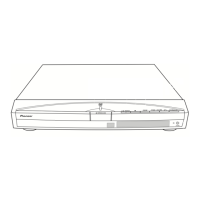
Illustration of external components and their assembly.
High-level functional overview of the receiver's main components.
Shows external and internal connections between major assemblies.
Schematic details for the tuner block and associated circuitry.
Schematic details for the DMUX block and related components.
Schematic details for SDRAM and memory interface circuitry.
Schematic details for AV switch and audio processing circuits.
Schematic details for control and power interface circuits.
Schematic of the power supply unit and its components.
Oscilloscope waveform examples for key test points.
Component layout and connection points on the main PCB.
Identifies major assemblies like Main and Power boards.
Lists semiconductors, coils, filters, and capacitors for the tuner.
Lists semiconductors, coils, filters, and capacitors for the DMUX.
Procedures for diagnosing issues, including check mode and LED status.
Flowcharts for diagnosing and resolving various hardware problems.
Details on key integrated circuits, their pinouts, and block diagrams.
Guidelines for handling and reflowing BGA components.
Important warnings and precautions for servicing PCBs.
Identifies test points and corresponding waveform numbers for diagnostics.
Instructions for using download.exe for firmware updates.
Guide to operating GA-0015B for checking IRD functionality.
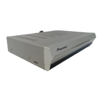
Identifies controls and indicators on the front panel.
Identifies connectors and ports on the rear panel.
Explains the purpose and operation of each button on the remote.