Do you have a question about the Pioneer DV-S755AI and is the answer not in the manual?
| Video Output | Composite, S-Video, Component |
|---|---|
| Dimensions | 430 x 300 x 80 mm |
| Weight | 3.5 kg |
| DVD/CD Text | Yes |
| Progressive Scan | Yes |
| Video D/A Converter | 10-bit / 27MHz |
| THX Certified | No |
| Dolby Digital Output | Yes |
| DTS Output | Yes |
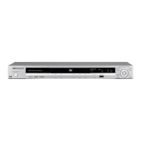
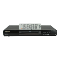
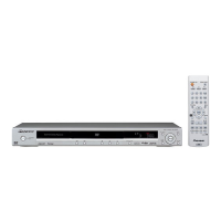
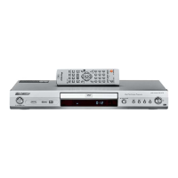
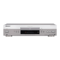
| Type | DVD Player |
| Signal-to-Noise Ratio | 115 dB |
| Output Level | 2 Vrms |
| Audio Formats Supported | Dolby Digital, DTS, PCM |
| Audio Output | Digital Coaxial, Optical |
| Audio D/A Converter | 24-bit |
| Playback Formats | CD |
| Channels | 2 |
Guidelines for conforming to product safety regulations during servicing.
Procedures for maintaining original product performance through adjustments.
High-level functional block diagram of the player's components.
Schematic diagrams covering the DVDM assembly (FTS, FR, EBY/AV1, VENC blocks).
Schematic diagrams covering the JACB assembly (Audio and Video blocks).
Schematic diagram of the SACDB assembly.
Schematic diagram of the power supply unit.
Oscilloscope waveforms for DVDM and JACB assemblies.
Lists the specific adjustment items and their locations on the mechanism.
Outlines points requiring adjustment when replacing specific parts.
Instructions on how to enter and operate the device's test modes.
Details on performing mechanical adjustments like Tangential and Radial Height.
Step-by-step guide for coarse adjustment of tangential and radial height.
Covers diagnostic functions, including self-diagnosis and error codes.
Instructions for setting unique ID numbers and data for regional compatibility.
Method to diagnose pickup defects by checking laser diode current values.
Explains the various displays and codes shown during test mode operation.
Details on self-diagnosis functions, mechanism error history, and check items.
Explains the functionality and indications within the service mode.
Lists and explains error codes displayed on the FL and remote control units.
Identifies test points and expected waveforms on the DVDM assembly.
Step-by-step guide to diagnose and resolve common player issues.
Procedure to diagnose audio signals from the DVDM assembly.
Steps to diagnose SACD and DSP block issues on the SACDB assembly.
Pin functions specifically for test mode operations.