EasyManua.ls Logo

Pioneer FH-M8527ZT-91 ES User Manual

Pioneer FH-M8527ZT-91 ES
85 pages
To Next Page IconTo Next Page
Page #1 background imageLoading...
Page #1 background image
PIONEER CORPORATION 4-1, Meguro 1-Chome, Meguro-ku, Tokyo 153-8654, Japan
PIONEER ELECTRONICS (USA) INC. P.O.Box 1760, Long Beach, CA 90801-1760 U.S.A.
PIONEER EUROPE NV Haven 1087 Keetberglaan 1, 9120 Melsele, Belgium
PIONEER ELECTRONICS ASIACENTRE PTE.LTD. 253 Alexandra Road, #04-01, Singapore 159936
C PIONEER CORPORATION 2002
K-ZZA. AUG. 2002 Printed in Japan
ORDER NO.
CRT2921
RECEIVER ASSY, RADIO
Service
Manual
TOYOTA
FH-M8527ZT/ES
FH-M8527ZT ES
FH-M8527
ZT-91 ES
FH-M8627ZT ES
FH-M8627ZT-91
ES
FH-M8527ZT CS
FH-M8527ZT-91 CS
VEHICLE DESTINATION PRODUCED AFTER TOYOTA PART No. ID No. PIONEER MODEL No.
LAND CRUISER Middle Near East, August 2002 86120-60530 P7809 FH-M8527ZT/ES
General Area(L) FH-M8527ZT-91/ES
LAND CRUISER Australia, August 2002 86120-60520 P7810 FH-M8627ZT/ES
General Area(R) FH-M8627ZT-91/ES
LAND CRUISER Central/South America August 2002 86120-60540 P7815 FH-M8527ZT/CS
FH-M8527ZT-91/CS
For details, refer to "Important symbols for good services".
w
w
w
.
x
i
a
o
y
u
1
6
3
.
c
o
m
Q
Q
3
7
6
3
1
5
1
5
0
9
9
2
8
9
4
2
9
8
T
E
L
1
3
9
4
2
2
9
6
5
1
3
9
9
2
8
9
4
2
9
8
0
5
1
5
1
3
6
7
3
Q
Q
TEL 13942296513 QQ 376315150 892498299
http://www.xiaoyu163.com

Table of Contents

Question and Answer IconNeed help?

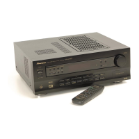
Do you have a question about the Pioneer FH-M8527ZT-91 ES and is the answer not in the manual?

Pioneer FH-M8527ZT-91 ES Specifications

General IconGeneral
CategoryReceiver
Power Output50W x 4
Built-in BluetoothYes
USB PortYes
AUX InputYes
CD PlayerYes
AM/FM TunerYes
Display TypeLCD
Remote ControlYes

Summary

SAFETY INFORMATION

Product safety

Adherence to regulations and safety during servicing.

Lubricants, glues, and replacement parts

Proper application of lubricants, glues, and use of replacement parts.

Cleaning

Proper cleaning of optical pickups, heads, and lenses.

Adjustments

Maintaining original performance through proper adjustments.

Shipping mode and shipping screws

Protecting the product during transit.

1. SPECIFICATIONS

2. EXPLODED VIEWS AND PARTS LIST

2.1 EXTERIOR(FH-M8527ZT/ES, CS) SECTION PARTS LIST

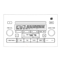
Parts list for exterior components.

2.2 EXTERIOR(FH-M8627ZT/ES)

2.3 CD MECHANISM MODULE

2.4 CASSETTE MECHANISM MODULE

3. BLOCK DIAGRAM AND SCHEMATIC DIAGRAM

3.1 BLOCK DIAGRAM

Visual representation of the system's functional blocks.

3.2 OVERALL CONNECTION DIAGRAM(GUIDE PAGE)

3.3 KEYBOARD UNIT

3.4 CD MECHANISM MODULE

● Waveforms REF.2.1

3.5 CASSETTE MECHANISM MODULE

4. PCB CONNECTION DIAGRAM

4.1 MAIN UNIT

Connection diagram for the main unit PCB.

4.2 KEYBOARD UNIT

4.3 CD MECHANISM MODULE

4.4 CASSETTE MECHANISM MODULE

5. ELECTRICAL PARTS LIST

6. ADJUSTMENT

6.1 CONNECTION DIAGRAM

Connection diagram for adjustment procedures.

6.2 AUDIO ADJUSTMENT

Connection Diagram

Connection diagram for audio adjustment.

DOLBY B NR ADJUSTMENT

Adjustment procedure for Dolby B NR.

6.3 TEST MODE

6.4 CD ADJUSTMENT

1) Precautions

Important precautions before performing CD adjustments.

2) Test Mode

How to enter and use the test mode for CD mechanism adjustment.

Flow Chart

6.5 CHECKING THE GRATING AFTER CHANGING THE PICKUP UNIT

• Checking Procedure

Step-by-step instructions for checking the grating.

6.6 ERROR CODE

(1) Basic Indication Method

Method of indicating error codes on the display.

(2) Error Code List

Detailed list of error codes, their causes, and details.

New Test Mode

(1) Shifting to the New Test Mode

Steps to enter the new test mode.

(2) Key Correspondence

Key operations and their corresponding new test mode functions.

(3) Cause of Error and Error Code

Explanation of error causes and associated codes.

(4) Display of Operational Status during Setup

(5) Display Examples

6.7 AVC-LAN DIAGNOSIS MODE

(1) Key operations for Diagnosis IN

Key operations for entering diagnosis mode.

(2) Key operations

Key operations for checking system responses.

(3) Key operations for entering Service check mode

Steps to enter service check mode.

(4) Key operations for entering the details display mode

Steps to enter the details display mode.

(5) Key operations for returning to the service check mode

How to exit sub-modes and return to service check mode.

(6) Clearing the Memory data

Procedure to clear diagnosis memory data.

Diagnosis code table

7. GENERAL INFORMATION

7.1 DIAGNOSIS

Information related to diagnosis.

7.1.1 DISASSEMBLY

Mechanical Unit Disassembly Procedures

Handling the Mechanical Unit

Proper methods for handling the mechanical unit.

Top and Bottom Frame Removal

Steps to remove the top and bottom frame.

Guide Arm Assy Removal

Steps to remove the guide arm assembly.

Component Removal Procedures

Control Unit Removal

Steps to remove the control unit.

Loading Arm Assy Removal

Steps to remove the loading arm assembly.

Pickup Unit Removal

Steps to remove the pickup unit.

7.1.2 CONNECTOR FUNCTION DESCRIPTION

7.2 PARTS

7.2.1 IC

List of integrated circuits.

7.2.2 DISPLAY

7.3 EXPLANATION

7.3.1 SYSTEM BLOCK DIAGRAM

Block diagram illustrating the overall system architecture.

7.3.2 OPERATIONAL FLOW CHART

7.4 CLEANING

8. OPERATIONS

Related product manuals