EasyManua.ls Logo

Pioneer PD-F25 User Manual

Pioneer PD-F25
38 pages
To Next Page IconTo Next Page
Page #1 background imageLoading...
Page #1 background image
Service
Manual
|=
FILE-TYPE
CD
PLAYER
PD-F25
ORDER
NO.
RRV
1667
THIS
MANUAL
IS
APPLICABLE
TO
THE
FOLLOWING
MODEL(S)
AND
TYPE(S).
PIONEER
ELECTRONIC
CORPORATION
RVICE,
INC.
PIONEER
ELECTRONICS
SE
|
yee
[pore]
_—_PomerRequement
|
amare
A
CONTENTS
1.
SAFETY
INFORMATION
....0..
cece
cscs
cesses
erensereeeees
2
2.
EXPLODED
VIEWS,
PACKING
AND
PARTS
LIST
......
3
3.
SCHEMATIC
AND
PCB
CONNECTION
DIAGRAMS
.
12
4:-"PGB
PARTS
LIST
2i03...ctnae
cian
dated
23
5.
ADJUSTMENTS.
00...
cece
esecneeeeceeteeeneseesaneeneree
25
6.
FL
INFORMATION
....00.
ccc
certs
cee
eeeeeneseneeneree
30
7.
IC
INFORMATION
00.
eeeeerettseeeeeeneteeenes
31
8.
OPERATIONAL
DESCRIPTION
...........
ccc
seeeeseetees
33
9.
NEW
FUNCTIONS
...0
oe
cca
cee
ence
ceeeteenenseeee
35
10.
BLOCK
DIAGRAN
..........
eee
ec
eee
rererteceeeteneeeeeees
36
11.
DISASSEMBLY
0000...
cseereeceeseneeesereeneesenees
37
12.
PANEL
FACILITIES
.000.o
ee
cree
reeetaneecnees
38
13.
SPECIFICATIONS
...0..
cece
cee
neseeeteeesseneseneesenee
38
P.O.Box
1760,
Long
Beach,
CA
90801-1760,
U.S.A.
PIONEER
ELECTRONIC
[EUROPE]
N.V.
Haven
1087,
Keetberglaan
1,
9120
Melsele,
Belgium
PIONEER
ELECTRONICS
ASIACENTRE
PTE.
LTD.
501
Orchard
Road,
#10-00
Lane
Crawford
Place,
Singapore
0923
©
PIONEER
ELECTRONIC
CORPORATION
1996
4-1,
Meguro
1-Chome,
Meguro-ku,
Tokyo
153,
Japan
T-FZE
JULY
1996
Printed
in
Japan
Question and Answer IconNeed help?

Do you have a question about the Pioneer PD-F25 and is the answer not in the manual?

Pioneer PD-F25 Specifications

Power IconPower
power requirements (US model)AC120V, 60Hz
power requirements (UK model)AC220-230V, 50/60Hz
power consumption12W
Operating Environment IconOperating Environment
operating temperature+5°C - +35°C
operating temperature (Fahrenheit)+41°F - +95°F
Weight and Dimensions IconWeight and Dimensions
weight3.2 kg
external dimensions180 (W) x 250 (H) x 268 (D) mm
external dimensions (inches)7-1/16 (W) x 9-13/16 (H) x 10-9/16 (D) in.

Summary

Safety Information

Safety Precautions

Safety checks for technicians and customers.

Product Safety Notice

Identifies parts with special safety characteristics and their importance.

Exploded Views and Parts List

Packing Contents

Details packing contents and parts list for the product.

Exterior Parts List

Lists external parts and their corresponding part numbers.

Front Panel Parts

Lists parts specific to the front panel assembly.

GM Mechanism Parts

Lists parts for the GM Mechanism assembly.

Servo Mechanism Parts

Lists parts for the Servo Mechanism assembly.

Schematic and PCB Diagrams

Schematic Diagram Notes

Notes on interpreting schematic diagrams and ordering parts.

PCB Diagram Notes

Notes on interpreting PCB diagrams and comparing them to schematics.

Circuit Board Assemblies

Details PCB layouts for various internal board assemblies.

Waveform Analysis

PCB Parts Listing

Assembly Parts List

Lists main assemblies and their part numbers.

Semiconductor Parts

Lists semiconductor components for various boards.

Capacitor Parts

Lists capacitor parts and their part numbers.

Resistor Parts

Lists resistor parts and their part numbers.

Adjustment Procedures

Adjustment Preparations

Lists necessary jigs, measuring instruments, and adjustment points.

Test Mode and Adjustment Locations

Details how to start/cancel test mode and adjustment locations.

Focus Offset Check and Adjustment

Procedure to check and adjust focus offset.

Pickup Tilt Adjustment

Procedure for adjusting pickup tilt in radial and tangential directions.

RF Level Check

Procedure for checking the RF signal level.

Focus Servo Loop Gain

Procedure for adjusting focus servo loop gain.

Tracking Servo Loop Gain

Procedure for adjusting tracking servo loop gain.

FL Display Information

FL Display Pin Location

Diagram showing pin locations on the FL tube.

FL Display Anode Grid Assignment

Assignment of anode grids for display segments.

IC Pin Information

PD4664A IC Pin Functions

Pin functions for the CD Control IC.

PD4664A IC Operation Modes

Continued pin functions and operation modes for PD4664A IC.

Operational Description

Power-On Setup Operation

Describes the initial setup and power-on sequence.

Play Mode Operation

Describes the operational steps when the unit is in Play Mode.

New Functions

Extension Function (AUX/CDII)

Details the AUX/CDII extension function.

Best Collection Memory

Explains the memory function for storing favorite tunes.

Previous Disc Scan

Describes the function to scan and memorize previous discs.

System Block Diagram

Disassembly Instructions

Front Panel Disassembly

Steps for disassembling the front panel.

CD Loading Mechanism Disassembly

Steps for disassembling the CD loading mechanism.

Panel Facilities and Controls

Front Panel Controls and Indicators

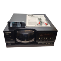
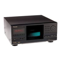
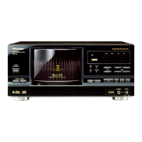
Identifies controls and indicators on the front panel.

Remote Control Unit Buttons

Identifies buttons on the remote control unit.

Product Specifications

Related product manuals