Do you have a question about the Pioneer PD-F705 and is the answer not in the manual?
Essential safety checks, including leakage current testing, for technicians.
Information on special safety characteristics of replacement parts.
Compares construction differences across different model types.
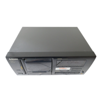
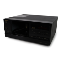
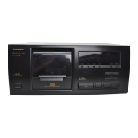
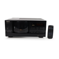
Details external parts and their variations by model type.
Exploded view and parts list for the GM mechanism assembly.
Exploded view and parts list for the GM slot-in mechanism assembly.
Schematics and assembly details for key PCB units.
Schematic and PCB connection diagrams for GM mechanism assemblies.
Compares part numbers for Mother PCB Assy across different model types.
Detailed parts lists for multiple PCB assemblies, covering various types.
Parts lists for further PCB assemblies, including common types.
Lists necessary jigs, measuring instruments, and test discs for adjustments.
Procedure for test mode operation and identification of adjustment points.
Covers focus offset, tracking error balance, pickup tilt, and RF level checks.
Procedures for adjusting focus and tracking servo loop gains.
Information, block diagram, and pin arrangement for the CXD2508AQ IC.
Details on the FL display tube, including pin location, anode grid, and pin assignments.
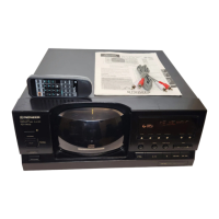
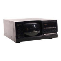
Overview of front panel buttons, switches, indicators, and display elements.
Details on type, power requirements, and physical dimensions.
Technical specifications for audio performance, including frequency response.
Information on output terminals and included accessories.
| Type | CD Player |
|---|---|
| Weight | 6.3 kg |
| Frequency Response | 2 Hz - 20 kHz |
| Channels | 2 |
| Output Voltage | 2.0 V |
| Power Consumption | 15 W |
| Playback Modes | Repeat, Random, Program |
| Digital Output | Optical |
| Dynamic Range | 96 dB |
| Signal-to-Noise Ratio | 102 dB |
| Total Harmonic Distortion | 0.003 % |