Do you have a question about the Pioneer PDP-505PE and is the answer not in the manual?
Product warnings, California Proposition 65 notice, and Canadian model fuse symbol notice.
Essential safety measures for service technicians during repairs.
Measuring resistance of exposed metal parts with AC plug removed.
Measuring current from exposed metal parts with AC power connected.
Importance of using specified parts with special safety characteristics.
Identifying hazardous AC power points without transformer isolation.
Identifying areas with voltages over 100V, posing shock risk.
Procedure for safely discharging VSUS voltage.
Adherence to safety regulations and maintaining a safe work environment.
Guidelines for adjustments, lubricants, cleaning, and shipping.
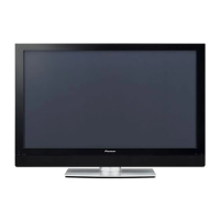
Technical specifications for the PDP-505PE model.
Technical specifications for the PRO-505PU model.
List of accessories provided with the unit.
Exploded diagram and parts list for the packing of the unit.
Parts list for packing, cross-referenced with contrast table.
Table detailing differences in packing parts across models.
Exploded view showing components of Chassis Section 1.
Detailed list of parts for Chassis Section 1.
Exploded view showing components of Chassis Section 2.
Detailed list of parts for Chassis Section 2.
Exploded view showing components of the Frame Section.
Detailed list of parts for the Frame Section.
Exploded view showing components of the Multi Base Section.
Detailed list of parts for the Multi Base Section.
Exploded view showing components of the Rear Section.
Parts list for the rear section.
Table detailing differences in rear section parts.
Exploded view showing components of the Front Section.
Parts list for the front section.
Table detailing differences in front section parts.
Parts list for the Panel Chassis (50) Assy.
Parts list for the PDP Service Assy 505P.
Comprehensive block diagram of the entire system's signal flow.
Block diagram detailing signals and components within the 50 Y Drive Assy.
Block diagram detailing signals and components within the 50 X Drive Assy.
Block diagram illustrating signal processing within the Panel IF Assy.
Voltages and signal details for the Power Supply Unit connector (CN4001).
Voltages and signal details for Media Receiver connectors (CN4002, CN4003).
Voltages and signal details for the HD Audio Amplifier Assy connector (CN4009).
Voltages and signal details for Panel LED/IR/Key Control Assy connectors (CN4010, CN4801).
Voltages and signal details for the Digital Video Assy connector (CN4004).
Further voltages and signal details for the Digital Video Assy connector (CN4004).
Block diagram of the Digital Video Assy, showing its integrated components.
Voltages and signal details for CN5601 on the Digital Video Assy.
Voltages and signal details for CN5602 on the Digital Video Assy.
Block diagram and IC functions for the HD Audio Amplifier Assy.
Oscilloscope waveforms for key signals in the Digital Video Assy.
Waveforms related to the Digital IF block.
Oscilloscope waveforms for key signals in the Panel IF Assy.
Waveforms related to the TMDS RX block.
Waveforms for X SUS, Y Logic, and Y SUS blocks of drive assemblies.
Waveforms for the ADR Resonance Block of the 50 Address Assy.
Waveforms for the ADR Logic Block of the 50 Address Assy.
Overall list of major assemblies and their part numbers.
Semiconductors, passive, and other components for the 50 Address Assy.
Semiconductors, passive, and other components for the 50 Scan A Assy.
Semiconductors, passive, and other components for the 50 Scan B Assy.
Semiconductors, passive, and other components for the Panel IF Assy.
Resistors and other components for the Digital Video Assy (IF Block).
Semiconductors, switches, capacitors, resistors for the Module UCOM Block.
Semiconductors, capacitors, resistors for the Panel Flash Block.
Semiconductors, coils, capacitors, resistors for the IC4 Block.
Semiconductors, capacitors, resistors, and others for the HD Audio Amplifier Assy.
Coils, filters, capacitors, and resistors for the HD SP Terminal Assy.
Semiconductors, coils, and filters for the Panel LED Assy.
Switches, relays, and others for the Panel Key Assy.
Semiconductors, coils, capacitors, resistors, others for Key Control Assy.
Semiconductors, capacitors, resistors, others for Panel IR Assy.
Semiconductors, capacitors, resistors, others for Panel Sensor Assy.
Semiconductors, capacitors, resistors, others for 50 X Drive Assy.
Semiconductors, capacitors, resistors for 50 X Resonance Block.
Miscellaneous parts for the 50 Y Drive Assy.
Semiconductors for the 50 Y Logic Block.
Capacitors and resistors for the 50 Y Logic Block.
Note regarding the Power Supply Unit having no service parts.
Semiconductors, coils, capacitors, resistors, others for 50 Y Scan Block.
Semiconductors, capacitors, resistors for 50 Y Resonance Block.
Semiconductors for Y D-Dcon Block.
Resistors for the Address CN Block.
Miscellaneous parts including connectors and heatsinks.
Guidelines for adjustments when assemblies or parts are replaced.
Specific assemblies that need adjustment after replacement or repair.
Procedure to readjust control signal timing for Drive Assys.
Table of specified delay times, input/output signals, and adjustment VRs.
Diagram showing the connection setup for RS232C commands.
Commands for adjusting parameters like ABL, FOCUS, MASK MODE, and FREQUENCY.
Commands for obtaining system status, panel info, and logs.
Commands for panel adjustments, system control, SRS, and TruBass.
Commands for Vofs, Volume, Vsus, and White Balance adjustments.
Retrieving ABL, electronic-control, and drive-system adjustment values.
Obtaining the serial number of the panel.
Obtaining the power-down point log from the panel.
Obtaining panel white-balance adjustment values.
Obtaining unit information, including software version.
Obtaining information on the unit's status.
Details on power-down points and their meanings.
Obtaining information on shutdown records and subcategories.
Adjusting Vsus and Vofs voltages after panel replacement.
Clearing hour meter, pulse meter, and other logs after panel replacement.
Methods for clearing panel logs using RS232C commands or Factory menu.
Illustration showing the placement of all PCBs within the unit.
Table correlating LED status with operation states and abnormalities.
Identifying abnormalities by LED flash count for shutdown/power-down.
Specific LED behaviors during shutdown due to various failures.
Specific LED behaviors during power-down due to protection circuits.
Block diagram illustrating the shutdown signal flow.
Detailed table linking LED flash counts to specific failures and defective parts.
Instructions for accessing the Factory mode using the remote control.
Using OSD to refer to power-down and shutdown logs.
Data related to MD-IIC subcategories for shutdown diagnosis.
Display and conversion of temperature data from the panel sensor.
Checking the product's serial number via the Factory menu.
Methods for operating the unit when the Media Receiver is not connected.
How drive-system voltage is compensated for temperature.
Overview of adjustment data backup to EEPROM.
List of specific data items backed up.
Steps for automatic and RS232C-command-based data backup.
Guidelines for reusing a repaired Digital Video Assy.
Handling simultaneous replacement of Digital Video and Panel IF Assys.
Confirming adjustment status and downloading data from backup ROM.
Step-by-step procedure for W/B adjustment using RS232C commands.
Procedure to clear data in the Digital Video Assy ROM.
Guide for diagnosing issues like no power, key input errors, or screen abnormalities.
Step-by-step instructions for removing the rear and front cases.
Steps for removing X Connector A and B Assys.
Steps for removing 50 Scan A and B Assys.
Steps for removing the Multi Base Section.
Information on BA10393F and BA10358F ICs, including pin arrangements.
Information on BA8274F, including block diagram and pin functions.
Block diagram for BA8274F.
Detailed pin function for BA8274F.
Information on NJM2195L, including pin arrangement and block diagram.
Pin arrangement for NJM2195L.
Block diagram for NJM2195L.
Information on MBM29PL160BD, including block diagram.
Block diagram for MBM29PL160BD.
Information on SII169CTG100, including pin arrangement and block diagram.
Pin arrangement for SII169CTG100.
Block diagram for SII169CTG100.
Information on STK795-512A, including block diagram.
Block diagram for STK795-512A.
Information on STK795-513A, including block diagram.
Block diagram for STK795-513A.
Information on LA4625, including block diagram.
Block diagram for LA4625.
Information on M30622FH8PGP, including pin function.
Pin function details for M30622FH8PGP.
Pin function details for M30622FH8PGP.
Pin function details for PEG054A (IC5401), pages 1-10.
Pin arrangement for AN16021A-K Mod Ucom.
Pin function details for AN16021A-K (Part 1).
Pin function details for AN16021A-K (Part 2).
Diagram showing front panel controls and indicators.
Diagram showing rear panel terminals and connections.
| Screen Size | 50 inches |
|---|---|
| Display Type | Plasma |
| Resolution | 1366 x 768 |
| Aspect Ratio | 16:9 |
| Contrast Ratio | 10000:1 |
| Response Time | 0.001 ms |
| Viewing Angle | 160 degrees |
| Inputs | HDMI, Component, Composite, S-Video |






 Loading...