EasyManua.ls Logo

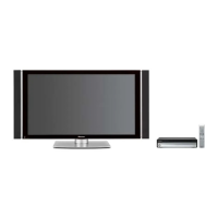
Pioneer PDP-506PG User Manual

Pioneer PDP-506PG
99 pages
To Next Page IconTo Next Page
Page #1 background imageLoading...
Page #1 background image
ORDER NO.
PIONEER CORPORATION 4-1, Meguro 1-chome, Meguro-ku, Tokyo 153-8654, Japan
PIONEER ELECTRONICS (USA) INC. P.O. Box 1760, Long Beach, CA 90801-1760, U.S.A.
PIONEER EUROPE NV Haven 1087, Keetberglaan 1, 9120 Melsele, Belgium
PIONEER ELECTRONICS ASIACENTRE PTE. LTD. 253 Alexandra Road, #04-01, Singapore 159936
PIONEER CORPORATION 2005
ARP3309
T – ZZY SEPT. 2005 Printed in Japan
THIS MANUAL IS APPLICABLE TO THE FOLLOWING MODEL(S) AND TYPE(S).
Model
Type
Power Requirement
Remarks
PDP-506PE WYVIXK AC220 - 240V
PDP-506PG TLDPFT AC110 - 240V
PRO-506PU KUCXC AC120V
PDP-506PE
PLASMA DISPLAY
This service manual should be used together with the following manual(s):
Model No. Order No. Remarks
PDP-506PE/WYVI ARP3267 SAFETY INFORMATION, EXPLODED VIEWS AND PARTS LIST, BLOCK DIAGRAM,
PCB PARTS LIST, ADJUSTMENT, IC INFORMATION etc.
PDP-506PG
PRO-506PU
Question and Answer IconNeed help?

Do you have a question about the Pioneer PDP-506PG and is the answer not in the manual?

Pioneer PDP-506PG Specifications

General IconGeneral
Screen Size50 inches
Display TypePlasma
Resolution1366 x 768
Aspect Ratio16:9
Brightness1000 cd/m²
Contrast Ratio4000:1
Viewing Angle160°
Response Time0.001 ms
Input PortsHDMI, Component, Composite, S-Video, VGA

Summary

SAFETY INFORMATION

Leakage Current Testing

Procedures for testing AC leakage current (cold and hot checks).

SAFETY PRECAUTIONS

PRODUCT SAFETY NOTICE

Charged Section

High Voltage Generating Point

[Important Check Points for Good Servicing]

1. SPECIFICATIONS

2. EXPLODED VIEWS AND PARTS LIST

2.1 PACKING SECTION

2.2 REAR SECTION

2.3 FRONT SECTION

2.4 CHASSIS SECTION (1/2)

2.5 CHASSIS SECTION (2/2)

2.6 PDP SERVICE ASSY 506P (AWU1134)

3. BLOCK DIAGRAM AND SCHEMATIC DIAGRAM

3.1 OVERALL CONNECTION DIAGRAM

3.2 OVERALL BLOCK DIAGRAM

3.3 50 ADDRESS ASSY

3.4 50 SCAN A and B ASSYS

3.5 50 X DRIVE, SUS CLAMP 1 and SUS CLAMP 2 ASSYS

3.6 50 Y DRIVE ASSY

3.7 HD DIGITAL ASSY

3.8 HD AUDIO ASSY

3.9 POWER SUPPLY UNIT

3.10 WAVEFORMS

5. PCB PARTS LIST

LIST OF WHOLE PCB ASSEMBLIES

6. ADJUSTMENT

6.1 ADJUSTMENT REQUIRED WHEN THE SET IS REPAIRED OR REPLACED

6.2 RS-232C COMMAND

1. Connection

2. Command format

3. Definition of various commands

4. RS-232C command for module microcomputer

5. QUEST commands (for acquiring status)

■ Acquisition of panel statuses ••• [QS1]

Acquisition of panel operation data ••• [QS2]

Acquisition of other data on the panel ••• [QIP]

Acquisition of panel adjustment data (common data) ••• [QAJ]

Acquisition of ABL/WB adjustment data ••• [QPW]

Acquisition of parameters ••• [QPM]

Acquisition of PD logs ••• [QPD]

Acquisition of SD logs ••• [QSD]

Acquisition of input signal data ••• [QSI]

Setting for Factory mode permission/prohibition ••• [FAY/FAN] [PFY/PFN]

① Functions related to picture quality

② Functions related to panel protection

Backup function for adjustment values for the main unit ••• [FAJ/UAJ/CBU/BCP]

Factory presetting ••• [PFS]

Conversion charts for electronic VRs: Conversion chart for the Vofs

Conversion charts for electronic VRs: Conversion chart for the Vyprst (1/2)

Conversion charts for electronic VRs: Conversion chart for the Vyprst (2/2)

7.1.2 DIAGNOSIS OF SHUTDOWN/POWER-DOWN INDICATED BY LEDS

• Operation statuses indicated by LEDs

• PD (power-down) count

• SD (shut down) count

• Diagnosis of shutdown

• Power-down diagnosis (defective points)

7.1.3 OVERVIEW OF PANEL FACTORY MODE

Top screen of the Factory Menu for the main unit

Top screen of the Panel Factory

Configuration of Panel Factory mode

1. PANEL INFORMATION

2. PANEL WORKS

3. POWER DOWN

<Causes of power-down and corresponding OSD indications>

4. SHUT DOWN

<Causes of shutdown and corresponding OSD indications>

5. PANEL-1 ADJ

Key operation

<Drive-sequence indications and indications for the ABL/WB tables>

<Lower-layer items of PANEL-1 ADJ>

6. PANEL-2 ADJ

Key operation

<Lower-layer items of PANEL-2 ADJ>

7. PANEL REVISE

Key operation

<Lower-layer items of PANEL REVISE>

8. ETC.

Key operation

<Lower-layer items of ETC.>

9. MASK SETUP

Key operation

<Lower-layer items of MASK SETUP>

7.1.4 OPERATION WHEN THE MEDIA RECEIVER IS NOT CONNECTED

1. Operation-without-the-Media-Receiver mode

2. DVI mode

7.1.5 POWER ON/OFF FUNCTION FOR THE LARGE-SIGNAL SYSTEM

7.1.6 BACKUP WHEN THE MAIN UNIT IS ADJUSTED

1. When the HD DIGITAL Assy is replaced...

2. In a case where a HD DIGITAL Assy that was mounted...

3. In a case where the HD DIGITAL Assy is replaced...

7.1.7 HOW TO CLEAR HISTORY DATA

Clearing the PD history

Clearing the SD history

Clearing the data on the hour meter

Clearing the data on the pulse meter

Clearing the data on the number of power-ons

7.1.8 DISASSEMBLY

1 Rear Case (506)

2 Control Plate Section

3 Front Case Assy (506PE)

• When only the front case assy (506PE) is to be removed

• Note when the front case assy (506PE) is to be reattached

4 Front Chassis Η Assy (50)

5 SUS CLAMP 1 and 2 Assys

6 50 SCAN A and B Assys

7.2 IC

• List of IC

• Pin Arrangement (Top view)

• Block Diagram

A Pin Function

TC7SH08FUS1 (50 SCAN B ASSY : IC2807) - 2-input AND Gate

TC74VHC00FTS1 (50 X DRIVE ASSY : IC1002) - Quad 2-Input NAND Gate

AXF1140 (50 X DRIVE ASSY : IC1202) - X Mask Module

AXF1142 (50 X DRIVE ASSY : IC1101) (50 Y DRIVE ASSY : IC2101) - DK Module

TC74VHC08FTS1 (50 Y DRIVE ASSY : IC2003, IC2005) - Quad 2-input AND Gate

AXF1141 (50 Y DRIVE ASSY : IC2252, IC2253) - Y Mask Module

M62334FP (HD DIGITAL ASSY : IC3157) - 8-bit 4ch I2C Bus D-A Converter with Buffer Amplifier

TC74VHC123AFTS1 (HD DIGITAL ASSY : IC3160) - Dual Monostable Multivibrator/AFN/AFT Retriggerble

PST3610UR (HD DIGITAL ASSY : IC3304) - Reset IC

PEG122C (HD DIGITAL ASSY : IC3401) - LSI for PDP video processing (SEQUENCE PROCESSOR)

NJW1183L (HD AUDIO ASSY : IC3753) - FOCUS & SRS IC

8. PANEL FACILITIES

Front view

■ Rear view

Jigs list

Related product manuals