EasyManua.ls Logo

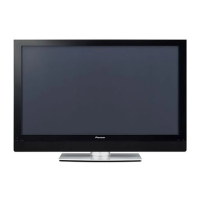
Pioneer PDP-5070PU User Manual

Pioneer PDP-5070PU
219 pages
To Next Page IconTo Next Page
Page #1 background imageLoading...
Page #1 background image
ORDER NO.
PIONEER CORPORATION 4-1, Meguro 1-chome, Meguro-ku, Tokyo 153-8654, Japan
PIONEER ELECTRONICS (USA) INC. P.O. Box 1760, Long Beach, CA 90801-1760, U.S.A.
PIONEER EUROPE NV Haven 1087, Keetberglaan 1, 9120 Melsele, Belgium
PIONEER ELECTRONICS ASIACENTRE PTE. LTD. 253 Alexandra Road, #04-01, Singapore 159936
PIONEER CORPORATION 2006
PDP-5071PU
ARP3354
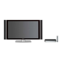
PLASMA DISPLAY SYSTEM
PDP-5071PU
PDP-5070PU
THIS MANUAL IS APPLICABLE TO THE FOLLOWING MODEL(S) AND TYPE(S).
This service manual should be used together with the following manual(s).
Model Type Power Requirement Remarks
PDP-5071PU KUCXC AC 120 V
PDP-5070PU KUCXC AC 120 V
Model No. Order No. Remarks
PDP-5071PU, PDP-5070PU ARP3355 SCHEMATIC DIAGRAM, PCB CONNECTION DIAGRAM
For details, refer to "Important Check Points for good servicing".
T-IZV AUG. 2006 printed in Japan

Table of Contents

Question and Answer IconNeed help?

Do you have a question about the Pioneer PDP-5070PU and is the answer not in the manual?

Pioneer PDP-5070PU Specifications

General IconGeneral
BrandPioneer
ModelPDP-5070PU
CategoryMonitor
LanguageEnglish

Summary

NOTES ON SERVICE VISIT

Service Safety Precautions and Information

General safety guidelines, warnings, and precautions for qualified service technicians.

Service Quick Reference and Factory Mode Guide

Provides quick reference for service visits, including notes, settings, and factory mode operations.

EXPLODED VIEWS AND PARTS LIST

BLOCK DIAGRAM AND SCHEMATIC DIAGRAM

Overall Connection Diagrams (Parts 1 & 2)

Illustrates the overall connection schematics for major assemblies, showing signal flow.

Overall Block Diagrams (Parts 1 & 2)

Illustrates the high-level functional blocks and their interconnections within the system.

Power Supply Unit Block Diagram

Block diagram illustrating the internal structure and operation of the Power Supply Unit.

DIAGNOSIS INFORMATION

Troubleshooting Flowcharts for System Diagnosis

Provides step-by-step flowcharts for diagnosing failures in various system parts.

DISASSEMBLY

ADJUSTMENT

Backup and Clearance of Adjustment and History Data

Procedures for backing up panel data and clearing various logs and history.

Adjustments After Service Panel Assembly Replacement

Specific adjustments required after replacing the service panel assembly.

Adjustments After Drive Assembly Replacement

Adjustments required after replacing 50X MAIN DRIVE and 50Y MAIN DRIVE Assys.

Power Supply Unit Replacement Procedure

Steps for changing connector settings after replacing the Power Supply Unit.

SERVICE FACTORY MODE

Service Factory Mode Outline and Operation

Overview of the Service Factory mode, including entry, exit, and general operations.

Factory Mode Menu Configuration and Options

Details the structure and adjustable parameters within the Factory mode menus.

LIST OF RS-232C COMMANDS

Specific RS-232C Commands Groups (QS1-DRV)

Lists and describes various commands like QS1, QS2, QIP, QAJ, QPW, QPM, QPD, QSD, QS6, QSI, QMT, QNG, DRV.

GENERAL INFORMATION

Large-Signal System Power Control

Procedure for controlling power to the panel driving system for diagnosis.
Related product manuals