EasyManua.ls Logo

Pioneer PDP-R05E User Manual

Pioneer PDP-R05E
213 pages
To Next Page IconTo Next Page
Page #1 background imageLoading...
Page #1 background image
ORDER NO.
PIONEER CORPORATION 4-1, Meguro 1-chome, Meguro-ku, Tokyo 153-8654, Japan
PIONEER ELECTRONICS (USA) INC. P.O. Box 1760, Long Beach, CA 90801-1760, U.S.A.
PIONEER EUROPE NV Haven 1087, Keetberglaan 1, 9120 Melsele, Belgium
PIONEER ELECTRONICS ASIACENTRE PTE. LTD. 253 Alexandra Road, #04-01, Singapore 159936
PIONEER CORPORATION 2004
POWER
ON STANDBY
TIMER
PDP-R05E
ARP3225
MEDIA RECEIVER
PDP-R05E
PDP-R05XE
PDP-R05FE
THIS MANUAL IS APPLICABLE TO THE FOLLOWINGMODEL(S) AND TYPE(S).
Please connect it to the PLASMA DISPLAY PDP-505PE or PDP-435PE for adjustment and
operation inspection.
Model Type Power Requirement Remarks
PDP-R05E WYVI AC220-240V
PDP-R05E WYVIXK AC220-240V
PDP-R05XE WYVIXK AC220-240V
PDP-R05FE WYVI AC220-240V
PDP-R05FE WYVIXK AC220-240V
For details, refer to "Important Check Points for Good Servicing".
Serial No.
Confirm it
WYVI SS
WYVIXK UK
T-ZZK NOV. 2004 printed in Japan

Table of Contents

Question and Answer IconNeed help?

Do you have a question about the Pioneer PDP-R05E and is the answer not in the manual?

Pioneer PDP-R05E Specifications

General IconGeneral
BrandPioneer
ModelPDP-R05E
CategoryReceiver
LanguageEnglish

Summary

SAFETY INFORMATION

SAFETY PRECAUTIONS

Safety checks for customer protection and technician safety.

PRODUCT SAFETY NOTICE

Details on safety-related characteristics of electrical and mechanical parts.

IMPORTANT CHECK POINTS FOR GOOD SERVICING

Product Safety

Conformity to product regulations and maintaining a safe servicing environment.

Adjustments

Maintaining original performance through optimum adjustments and confirmations.

SPECIFICATIONS

EXPLODED VIEWS AND PARTS LIST

PACKING SECTION

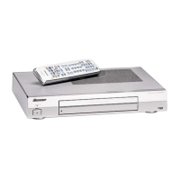
Details on the packing configuration and included parts.

EXTERIOR SECTION (1)

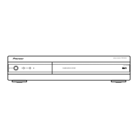
Exploded view and parts list for exterior components (part 1).

EXTERIOR SECTION (2)

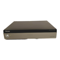
Exploded view and parts list for exterior components (part 2).

FRONT PANEL SECTION

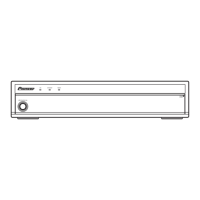
Exploded view and parts list for the front panel assembly.

BLOCK DIAGRAM AND SCHEMATIC DIAGRAM

BLOCK DIAGRAM

Overall block diagram illustrating signal flow and component interconnections.

MR MAIN BOARD ASSY

Block diagram for the MR Main Board Assembly.

AV BOARD ASSY

Block diagram for the AV Board Assembly.

POWER SUPPLY UNIT

Block diagram for the Power Supply Unit.

TUNER BOARD ASSY

Block diagram for the Tuner Board Assembly.

OVERALL WIRING CONNECTION DIAGRAM

Diagram showing all wiring connections between major assemblies.

PCB CONNECTION DIAGRAM

SW and MDR ASSYS

PCB connection diagrams for SW and MDR assemblies.

AV BOARD and SR ASSY

PCB connection diagrams for AV Board and SR assemblies.

FRONT and LED ASSY

PCB connection diagrams for Front and LED assemblies.

TUNER BOARD ASSY

PCB connection diagrams for the Tuner Board Assembly.

PCB PARTS LIST

LIST OF ASSEMBLIES

List of major assemblies with their part numbers for different models.

ADJUSTMENT

HOW TO ENTER SERVICE FACTORY MODE

Procedure to access the Service Factory Mode for adjustments.

POSSIBLE CASES WHERE READJUSTMENT IS REQUIRED

Conditions requiring readjustment after replacing assemblies or parts.

USING RS-232C COMMANDS

Guide for controlling the unit via RS-232C commands.

SERVICE FACTORY MODE

Explanation of operating in Service Factory mode and its functions.

INFORMATION mode

Operation items

Description of displayed items in the INFORMATION mode.

MR NG

Displays Media Receiver NG information and subcategory details.

FUNCTION CHECK mode

FAN

Controls and displays FAN speed and status.

INITIALIZE mode

UART SELCT

Selects UART settings for RS-232C communication.

LIST OF RS-232C COMMANDS

OUTLINE OF COMMANDS

GET Commands

Commands to retrieve model, version, and software information.

GENERAL INFORMATION

DIAGNOSIS

Troubleshooting guide for identifying and resolving issues.

EXPLANATION

PROCESSING IN ABNORMALITY

Explains procedures for handling abnormal operations of power supply and fan.

SEQUENCE

Describes the power-on sequence for the R05 series.

PARTS

IC

Lists integrated circuits (ICs) with their block diagrams and pin arrangements.

CLEANING

PANEL FACILITIES

Related product manuals