EasyManua.ls Logo

Pioneer PDP-R06U User Manual

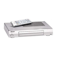
Pioneer PDP-R06U
47 pages
To Next Page IconTo Next Page
Page #1 background imageLoading...
Page #1 background image
Product Training
Guide
6th
Generation Plasma
Media Receivers
PRO-R06U
PDP-R06U
Technical Training Department
1925 E. Dominguez Street
Long Beach, CA 90810

Questions and Answers:

Pioneer PDP-R06U Specifications

General IconGeneral
BrandPioneer
ModelPDP-R06U
CategoryReceiver
LanguageEnglish

Summary

Pioneer Media Receiver Feature Comparison

R05U vs R06U Model Differences

Details functional changes and additions between Pioneer R05U and R06U models.

Home Gallery Functionality

Supported Media and File Formats

Lists supported memory media types and file format specifications for Home Gallery.

Home Gallery Features Overview

Highlights features like high-resolution display, fast browsing, and user interface.

System Power On Sequence

Power On Sequence Diagram

Illustrates the step-by-step process for powering on the device.

Technical Diagrams

Power Supply Unit Block Diagram

Shows the functional blocks of the power supply unit.

DTV Board Block Diagram

Illustrates the architecture and components of the DTV board.

Signal Flow Overview

Details signal paths for various inputs like DTV, HDMI, Analog, PC, and Component.

LED Indicators and Diagnostics

LED Lighting Patterns

Correlates unit status with specific LED flashing patterns.

Troubleshooting via LED Flashing

Lists potential defective points based on the number of LED flashes.

System Shutdown and Safety Notes

SD Shut Down Block Diagram

Illustrates the block diagram related to system shutdown.

System Outline and TRAP Switch

Explains HDCP for copyright protection and the TRAP switch function.

Service Factory Mode Operation

Entering and Operating Service Factory Mode

Details how to enter, operate, and manage user data in factory mode.

Remote Control Codes for Factory Mode

Lists remote control codes used for navigating service factory functions.

Service Factory Menu and Data

Service Factory Menu Structure

Outlines modes like INFORMATION, FUNC.CHECK, OPTION, INITIALIZE, and PANEL FACTORY.

Indications in Service Factory Mode

Displays main-item indications, SIG modes, and screen size selections.

INFORMATION Mode Operation Items

Details items displayed in INFORMATION mode, like versions and signal info.

MAIN NG and Temperature/Hour Meter

Displays main errors, shutdown causes, temperature, and total power-on time.

HDMI, Tuner, and DTV Signal Information

Shows input signal status for HDMI, Tuner, and DTV tuning.

Function Check Mode Operations

Allows checking functions like FAN speed and AFT action.

Option and Initialize Mode Settings

Covers settings for Peak Limiter, Antenna Mode, SG Mode, and Final Setup.

Disassembly and Reassembly

Unit Disassembly Steps

Guides for removing the metal bonnet and front panel section.

Component Removal Procedures

Instructions for removing the MR DTB Assy and Main PCB.

PC Card and US Model Specifics

Tips for PC card handling and US model specific notes during disassembly.

Comprehensive Troubleshooting Guide

Image Display Troubleshooting

Flowcharts for diagnosing issues with composite, S, TV, component, RGB, and PC signals.

Audio Output Troubleshooting

Steps to diagnose issues with monitor out and no sound from speakers or subwoofer.

DTB Operation Troubleshooting

Steps to diagnose and resolve issues with the DTB not operating.

Related product manuals