EasyManua.ls Logo

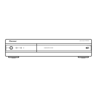
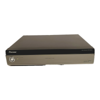
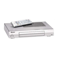
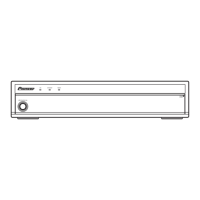
Pioneer PDP-R006FE User Manual

Pioneer PDP-R006FE
112 pages
To Next Page IconTo Next Page
Page #1 background imageLoading...
Page #1 background image
ORDER NO.
PIONEER CORPORATION 4-1, Meguro 1-chome, Meguro-ku, Tokyo 153-8654, Japan
PIONEER ELECTRONICS (USA) INC. P.O. Box 1760, Long Beach, CA 90801-1760, U.S.A.
PIONEER EUROPE NV Haven 1087, Keetberglaan 1, 9120 Melsele, Belgium
PIONEER ELECTRONICS ASIACENTRE PTE. LTD. 253 Alexandra Road, #04-01, Singapore 159936
PIONEER CORPORATION 2005
PDP-R06XE
ARP3275
MEDIA RECEIVER
PDP-R06XE
PDP-R06FE
THIS MANUAL IS APPLICABLE TO THE FOLLOWING MODEL(S) AND TYPE(S).
This service manual should be used together with the following manual(s).
Model Type Power Requirement Remarks
PDP-R06XE WYVIXK5 AC220-240V
PDP-R06FE WYVI5 AC220-240V
PDP-R06FE WYVIXK5 AC220-240V
Model No. Order No. Remarks
PDP-R06XE, PDP-R06FE ARP3276 SCHEMATIC DIAGRAM, PCB CONNECTION DIAGRAM
For details, refer to "Important Check Points for good servicing".
T-IZR AUG. 2005 printed in Japan

Table of Contents

Question and Answer IconNeed help?

Do you have a question about the Pioneer PDP-R006FE and is the answer not in the manual?

Pioneer PDP-R006FE Specifications

General IconGeneral
BrandPioneer
ModelPDP-R006FE
CategoryReceiver
LanguageEnglish

Summary

Safety Information

Safety Precautions and Notices

Details on safety precautions, warnings, and health/environmental notices for service technicians.

Important Check Points for Good Servicing

Product safety

Conformity to product regulations and maintaining a safe servicing environment.

Specifications

Block Diagram and Schematic Diagram

3.1 Overall Block Diagram

Overall block diagram illustrating the main system components and their connections.

Adjustment

6.1 Possible Cases Where Readjustment Is Required

Identifies scenarios requiring readjustment after assembly replacement.

6.4 Service Factory Mode

Procedures to enter and operate the service factory mode.

6.5 List of RS-232C Commands (Media Receiver)

Comprehensive list of RS-232C commands and their operations.

General Information

7.1 Diagnosis

Diagnostic procedures for identifying and resolving issues.

7.1.1 Troubleshooting

Step-by-step troubleshooting guides for common display problems.

Waveforms for Troubleshooting

Illustrations of signal waveforms for diagnostic purposes.

7.1.2 Disassembly

Step-by-step instructions for disassembling the unit.

Defective points assumed from the number of times of LED flashing

Correlation between LED flashing patterns and potential defects.

Parts

7.3.1 IC

List and diagrams of integrated circuits used in the unit.
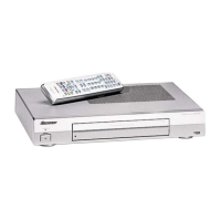
Panel Facilities

Related product manuals