EasyManua.ls Logo

Pioneer PDR-555RW Service Manual

Pioneer PDR-555RW
72 pages
To Next Page IconTo Next Page
Page #1 background imageLoading...
Page #1 background image
ORDER NO.
PIONEER ELECTRONIC CORPORATION 4-1, Meguro 1-Chome, Meguro-ku, Tokyo 153-8654, Japan
PIONEER ELECTRONICS SERVICE, INC. P.O. Box 1760, Long Beach, CA 90801-1760, U.S.A.
PIONEER ELECTRONIC (EUROPE) N.V. Haven 1087, Keetberglaan 1, 9120 Melsele, Belgium
PIONEER ELECTRONICS ASIACENTRE PTE. LTD. 501 Orchard Road, #10-00 Wheelock Place, Singapore 238880
PIONEER ELECTRONIC CORPORATION 1998
c
PDR-555RW
RRV1983
1. SAFETY INFORMATION
......................................
2
2. EXPLODED VIEWS AND PARTS LIST
................
4
3. SCHEMATIC DIAGRAM
.....................................
10
4. PCB CONNECTION DIAGRAM
..........................
32
5. PCB PARTS LIST
...............................................
44
6. ADJUSTMENT
....................................................
49
CONTENTS
7. GENERAL INFORMATION
................................
55
7.1 PARTS
.........................................................
55
7.1.1 IC
...........................................................
55
7.1.2 DISPLAY
................................................
67
8. PANEL FACILITIES AND SPECIFICATIONS
..
.69
T – IZK OCT. 1998 Printed in Japan
Type
Model
Power Requirement Remarks
PDR-555RW
KU/CA AC120V
MY AC220-230V
THIS MANUAL IS APPLICABLE TO THE FOLLOWING MODEL(S) AND TYPE(S).
COMPACT DISC RECORDER
FOR U.S. MODELS
NECESSARY INFORMATION FOR DHHS
RULES MARKED ON THE REAR BASE AND ON
THE TOP OF CD MECHANISM AS BELOW.
DANGER – LASER RADIATION WHEN OPEN.
AVOID DIRECT EXPOSURE TO BEAM.
Refer to the service guide RRV2055 for PDR-555RW.

Other manuals for Pioneer PDR-555RW

Question and Answer IconNeed help?

Do you have a question about the Pioneer PDR-555RW and is the answer not in the manual?
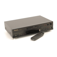
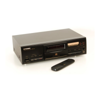
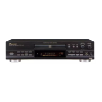
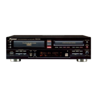
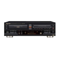
Pioneer PDR-555RW Specifications

General IconGeneral
TypeCD Recorder
Recording MediaCD-R, CD-RW
Audio Formats SupportedPCM
Remote ControlYes
Output Level2.0V
Playback FormatCD-R, CD-RW
Input ConnectorsAnalog, Digital (coaxial, optical)
Output ConnectorsAnalog, Digital (coaxial, optical)
Frequency Response20 Hz - 20 kHz

Summary

Safety Information

Safety Precautions

General safety warnings and procedures for technicians, including leakage current testing.

Leakage Current Check

Procedure to measure AC leakage current to earth ground to ensure safety compliance.

Product Safety Notice

Information on product safety characteristics and the importance of using specified replacement parts.

Label Check

Additional Laser Caution

Details about the laser interlock mechanism and potential exposure risks during servicing.

Exploded Views and Parts List

Schematic Diagram

Overall Connections, Loading A, B, and Servo Mech Assemblies

Shows overall interconnections between major assemblies like Pickup, Servo, and Loading units.

Servo Digital Assy (1/6)

Servo Digital (2/6) and Pickup Assemblies

RF Processor Block

Schematic diagram detailing the RF processor block and its components.

Servo Digital Assy (5/6)

Mecha. Control Micom Block

Schematic diagram of the mecha control microcomputer block.

Decoder Block

Schematic diagram detailing the decoder block and its components.

Digital Block

Schematic diagram of the digital signal processing block.

Servo Digital Assy (6/6)

Strategy Block

Schematic diagram detailing the strategy block and its components.

Audio (1/2) and Headphone Assemblies

Audio Assy (1/2)

D/A Block

Schematic diagram of the Digital-to-Analog conversion block.

Audio (2/2) and VR Assemblies

Audio Assy (2/2)

A/D Block

Schematic diagram of the Analog-to-Digital conversion block.

Power and Trans Assemblies

Function Assy

PCB Connection Diagram

PCB Parts List

Servo Digital Assy

Adjustment

Measuring Instruments

Lists necessary measuring instruments for performing adjustments.

Test Mode Operations

Explains entering Test Mode, operations, and playback procedures.

Adjustment 1 (Laser Diode Power Adjustment)

Playback Power Adjustment

Procedure and value for adjusting playback laser diode power.

Adjustment 1 (Continued)

CD-R Record Power Adjustment

Procedure and values for adjusting CD-R record power.

CD-RW Record Power Adjustment

Procedure and values for adjusting CD-RW record power.

Adjustment 2 (Servo System Adjustment)

Focus Offset Adjustment

Procedure and value for adjusting focus offset.

Adjustment 2 (Continued)

M-S Mix Ratio Adjustment

Procedure for adjusting the M-S mix ratio.

Focus Bias Adjustment

Procedure for adjusting focus bias.

Tracking Offset Adjustment

Procedure and value for adjusting tracking offset.

Panel Facilities and Specifications

Panel Facilities (Continued)

Remote Control Unit

Specifications (KU/CA Type)

Related product manuals