Do you have a question about the Pioneer SA-5800 and is the answer not in the manual?
Controls power supply to the amplifier.
Selects speaker systems A, B, or A+B.
Displays rated power level on the fluorescent display tube.
Indicate selected program source on the meter panel.
Accentuate bass at low volume levels.
Adjusts output level to speakers and headphones.
Allows listening through stereo headphones.
Adjusts bass and treble frequencies for sound shaping.
Balances volume between left and right audio channels.
Attenuates frequencies below 15Hz to suppress noise.
Selects the audio program source.
Monitor recording or playback from tape decks.
Details the 2-stage direct-coupled equalizer amplifier design.
Describes the pure complementary SEPP power amplifier circuit.
Explains circuit for eliminating click noise during power on/off.
Describes the fluorescent indicator tube drive circuit.
Instructions for removing side and top covers.
Procedure for removing the bottom plate.
Steps to remove knobs and the front panel assembly.
Procedure for setting the amplifier's idle current.
Steps to adjust the output power indicator levels.
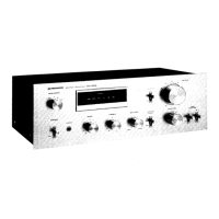
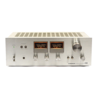
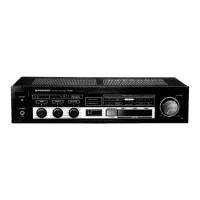
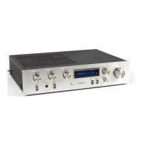
Identifies parts on the front panel.
Shows part locations after panel removal.
Identifies components visible from the top.
Shows connectors and terminals on the rear panel.
Lists miscellaneous parts like switches, fuses, and PC board assemblies.
Detailed circuit schematic diagram of the amplifier.
Diagrams showing connections between different PC boards.
Lists components for specific PC board assemblies.
Compares miscellaneous parts between SA-508/KU and SA-5800/KU.
| Total Harmonic Distortion | 0.05% |
|---|---|
| Input Sensitivity | 2.5mV (MM), 150mV (line) |
| Damping Factor | 30 |
| Speaker Load Impedance | 4Ω to 16Ω |
| Channel Separation | 50 dB |
| Type | Integrated Amplifier |
| Frequency Response | 20Hz to 20kHz |
| Output | Speakers |
| Dimensions | 420 x 150 x 269mm |