Do you have a question about the Pioneer SA-6300 and is the answer not in the manual?
Highlights 20W per channel output and low distortion characteristics using pure complementary OCL circuitry.
Features an IC equalizer section for minimized RIAA deviation and advanced fidelity with transistorized circuits.
Details line voltage compatibility and the process for changing voltage settings and replacing the fuse.
Explains connectivity for various program sources like turntables, tuners, and tape decks via rear panel input jacks.
Describes the ability to connect and select between two sets of speaker systems using the speaker selector switch.
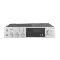
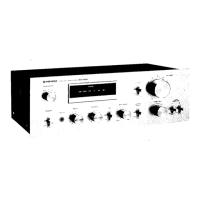
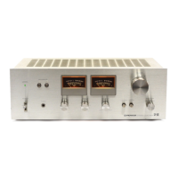
Notes the simple, elegant front panel for operational ease and availability of a matching stereo tuner.
Details the need for at least one pair of speakers and a program source of comparable quality to the SA-6300.
Advises against installing the unit in direct sunlight, humid/dusty areas, or on unstable supports to prevent damage.
Illustrates connections for turntable, tuner, tape deck, and speaker systems to the SA-6300.
Emphasizes observing channel and polarity for inputs/outputs and ensuring secure connections to prevent noise.
Explains the use of switched and unswitched AC outlets for powering other components up to 200W.
Connects turntable outputs to PHONO jacks and ground wire to GND terminal. Notes MM/MC cartridge compatibility.
Connects an AM/FM stereo tuner to the TUNER jacks using a connecting cord.
Describes using AUX jacks for auxiliary inputs like cartridge tape players or second tuners.
Details connections for recording (TAPE REC) and playback (TAPE PB), including DIN connector options.
Describes the POWER switch for turning the unit ON/OFF and the Pilot Lamp indicating power status.
Provides a PHONES jack for private listening, requiring the SPEAKERS switch to be OFF.
Explains the SPEAKERS switch for selecting speaker systems A, B, or both, and OFF for headphone use.
Details BASS & TREBLE controls for tone adjustment and BALANCE control for left/right volume balance.
Instructs to set TAPE MONITOR to ON for tape playback or recording monitoring.
Lists initial settings for controls like VOLUME, TAPE MONITOR, BALANCE, LOUDNESS, BASS/TREBLE, and SPEAKERS before powering on.
Step-by-step guide to playing records, including setting FUNCTION to PHONO and adjusting controls.
Instructions for using the tuner by setting FUNCTION to TUNER and adjusting volume and tone controls.
Guide for operating auxiliary sources connected to AUX jacks, setting FUNCTION to AUX and adjusting controls.
How to play tape using the TAPE PB jacks by setting TAPE MONITOR to ON and adjusting controls.
Explains monitoring recording through speakers/headphones by setting TAPE MONITOR to ON for 3-head decks.
Guide for duplicating tapes using two tape decks connected to AUX and TAPE terminals.
Process for recording from sources like PHONO or TUNER to the TAPE REC jacks.
Diagram and instructions for setting FUNCTION to PHONO and adjusting controls for record playback.
Diagram and instructions for setting FUNCTION to TUNER and adjusting controls for broadcast reception.
Diagram and instructions for setting FUNCTION to AUX and adjusting controls for auxiliary sources.
Diagram and instructions for tape playback, setting TAPE MONITOR to ON and adjusting controls.
Diagram and instructions for tape recording, setting FUNCTION and TAPE MONITOR for monitoring.
Checks for no sound: inspect power cord, connections, speaker connections, and switch positions.
Addresses high noise levels and distorted sound by checking ground wire, record condition, stylus, and turntable vibration.
Troubleshoots interference from power tools or radio stations and ensures proper station tuning.
Lists the quantities of ICs, transistors, and diodes used in the amplifier.
Details power output, harmonic distortion, bandwidth, and damping factor for the amplifier section.
Provides input sensitivity, impedance, output level, and impedance for various terminals.
Specifies frequency response for PHONO, TUNER/AUX/TAPE PB, and the range of BASS/TREBLE controls.
Details Hum & Noise levels and the effect of the Loudness Contour control at -40dB volume.
Includes power requirements, consumption, dimensions, and weight of the unit.
Lists the items included with the amplifier, such as operating instructions and connection cords.
| Total Harmonic Distortion | 0.1% |
|---|---|
| Input Sensitivity | 2.5mV (MM), 150mV (line) |
| Output | 150mV (line) |
| Speaker Load Impedance | 4Ω to 16Ω |
| Type | Stereo Amplifier |
| Frequency Response | 20Hz to 20kHz |
| Signal to Noise Ratio | 90dB (line) |
| Channel Separation | 50dB |