Do you have a question about the Pioneer SA-6500 II and is the answer not in the manual?
Lists ICs, transistors, and diodes used in the amplifier.
Details circuitry, power output, and frequency response.
Covers distortion, damping, tone controls, and hum/noise.
Includes power requirements, dimensions, and weight.
Descriptions of Bass, Treble, Volume, Balance, and Tone controls.
Details on Speakers, Function, Power, Loudness, and Tape Monitor switches.
Diagrams for connecting Turntable, Tuner, Tape decks, Speakers, and Headphones.
Shows AC cord connection, outlets, and grounding.
Block diagrams for Equalizer, Tone, and Power Amplifier stages.
Block diagrams for Power Supply and Protection circuits.
Explanations for switch symbols and control assignments.
Illustrates signal levels for PHONO and TUNER/AUX/TAPE inputs.
Illustrates signal levels for SPEAKER and HEADPHONE outputs.
Describes the Equalizer, Tone Control, and Power Amplifier circuits.
Explains the Muting and Speaker Protection circuits.
Instructions for removing the top cover.
Instructions for removing the bottom panel.
Instructions for removing the front panel.
Instructions for removing the AF amplifier assembly.
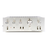
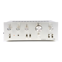
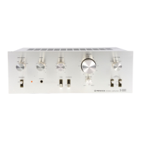
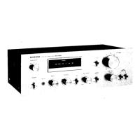
Labeled diagram of front panel components.
Labeled diagram of front components with panel removed.
Labeled diagram of top components with cover removed.
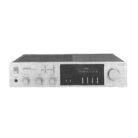
Labeled diagram of rear panel components.
Procedure and diagram for setting idle current.
Exploded view of the main exterior parts.
Exploded view of Part 1 components.
Exploded view of Part 2 components.
Exploded view of Part 3 components.
Detailed exploded view of Part 1.
Detailed exploded view of Part 2.
Detailed exploded view of Part 3.
Exploded view of the AF amplifier assembly.
Lists switches, transformer, capacitors, lamps, and fuses.
Shows external views of transistors, ICs, and thyristors.
Illustrates rotary switch rear and side views.
Provides the circuit diagram for the TA7136P1 IC.
Overall schematic diagram of the amplifier.
Detailed schematic for the AF amplifier assembly.
Diagram showing the Printed Circuit Board layout.
Detailed parts list for the AF amplifier assembly.
Lists resistors with their descriptions and part numbers.
Lists transistors, diodes, ICs, and varistors with part details.
Lists vinyl bag, instructions, pads, cover, pouch, and case.