Do you have a question about the Pioneer SX-3600 and is the answer not in the manual?
Details power output, distortion, damping factor, input/output specifications.
Lists sensitivity, selectivity, and signal-to-noise ratio for the AM tuner.
Provides specifications for FM tuner sensitivity, selectivity, and stereo separation.
Covers power requirements, consumption, dimensions, and weight of the unit.
Explains the power switch, speaker indicators, and power meter on the front panel.
Details the dial pointer, AM/FM tuning meter, and FM stereo indicator.
Describes the tuning knob, function indicators, headphone jack, and speaker switches.
Explains the bass, treble, balance, loudness, and volume controls.
Covers the mode/FM muting switch and tape monitor switches.
Describes the function selector for choosing audio input sources.
Describes the components and stages of the AM and FM tuner sections.
Details the equalizer amplifier and the power amplifier stages.
Explains the operation of the output power indicator circuit using an FL tube.
Instructions for removing the side boards and top plate.
Steps for detaching the bottom plate and removing the front panel.
Identifies parts on the front panel and with the panel removed.
Shows part locations on the top and rear panels of the unit.
Procedures for adjusting the FM tuner sensitivity and selectivity.
Steps for adjusting the FM multiplex decoder for optimal signal reception.
Instructions for adjusting the AM tuner for optimum sensitivity across its band.
Details idle current and output indicator adjustments for the power amplifier.
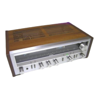
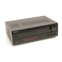
Lists and illustrates the external components of the unit.
Illustrates and identifies the internal components of the receiver.
Shows the physical appearance and pinouts of various transistors and ICs used.
Provides the complete circuit schematic for the SX-3600 receiver.
Shows how the printed circuit boards are interconnected within the unit.
A comprehensive list of all parts used in the SX-3600, with part numbers and descriptions.
| Tuning range | FM, MW |
|---|---|
| Total Harmonic Distortion | 0.3% |
| Damping Factor | 30 |
| Input Sensitivity | 2.5mV (MM), 150mV (line) |
| Output | 150mV (line) |
| Speaker load impedance | 4Ω to 16Ω |
| Semiconductors | 1 FET |