Do you have a question about the Pioneer SX-3900 and is the answer not in the manual?
Details power output, distortion, frequency response, input sensitivity, damping factor, hum and noise.
Details input sensitivity, overload level, output level, and distortion for phono and other inputs.
Details sensitivity, selectivity, signal-to-noise ratio, image and IF response, and antenna.
Covers output level/impedance, FM/AM modulation, semiconductors, power requirements, dimensions, and weight.
Lists types and quantities of ICs, FETs, transistors, diodes, and other components.
Covers power requirements, consumption, dimensions, and weight.
Lists operating instructions and FM T-type antenna.
Explains power switch, bass/treble controls, and tone switches for sound adjustment.
Details adaptor and tape duplicate/monitor switches for input selection and tape operations.
Describes balance, mode, volume, muting, headphone, speaker controls for audio output.
Explains low/high filters, power meter, dial pointer, and various indicators.
Covers tuning knob, tuning indicator, and frequency display functionality.
Details FM muting and Dolby FM switches for improved reception.
Covers brightness selector and function selector for source input.
Explains the loudness switch for accentuating bass/treble at low volumes.
Illustrates the signal path for FM and AM tuning circuits.
Shows the signal path for phono, AUX, tape, and tone controls.
Details front end, IF amp, detector, quartz-lock. Includes front end, IF stages, and quartz-lock operation.
Explains locking range limitation and multiplex decoder functions.
Describes the AM tuner components and AM stereo output.
Details phono equalizer and tone control circuits, including amplifier design and tone control configuration.
Describes differential amplifier, power stage, and bias control, including amplifier stages and bias servocontrol.
Details power indicator and frequency display circuits, including their respective circuit operations.
Shows counter IC block diagram and digit signal timing.
Details tuning and signal indicator circuits, covering tuning indicator and signal indicator operations.
Explains the circuit protecting speakers and amplifiers. Includes muting operation during power transitions.
Explains DC voltage and overload detection circuits as protection mechanisms.
Instructions for removing wooden cover, bottom plate, and front panel.
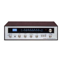
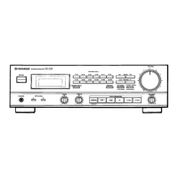
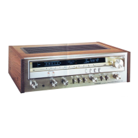
Identifies parts on the front and rear panels.
Shows the layout of interior components from the top.
Shows the layout of interior components from the bottom.
Procedures for power amplifier DC balance, idle current, and power indicator calibration.
Steps for adjusting FM tuner, multiplex decoder, and crystal detector.
Adjusting the frequency display for accuracy.
Detailed steps for adjusting the AM tuner section.
Shows the physical appearance of various semiconductors.
Lists semiconductors, fuses, lamps, switches, PC boards, and other parts.
Lists components specific to the tuner assembly.
Lists capacitors with part numbers.
Lists capacitors and resistors with part numbers.
Lists semiconductors, coils, and filters with part numbers.
Lists switches and tone amplifier components.
Lists capacitors and resistors for the tone amplifier.
Lists resistors and semiconductors with part numbers.
Lists components specific to the indicator assembly.
Lists capacitors for the indicator assembly.
Lists capacitors, resistors, and semiconductors with part numbers.
Lists other parts and specific assembly components.
Lists resistors, semiconductors, and other parts with part numbers.
Lists components for rectifier, speaker, switch, and headphone assemblies.
Shows an exploded view of external parts.
Lists interior components by key number, part number, and description.
Lists packing materials and operating instructions.
Service bulletin header for model, subject, and page reference.
Details the subject of the service bulletin regarding power amp resistors.
Lists specifications for the S/G type, noting differences from KU.
Compares semiconductors and fuses between KU and S/G types.
Compares lamps and switches between KU and S/G types.
Lists other PC boards, packing, and furnished parts.
Shows the PCB layouts for rectifier and fuse holder assemblies.
Shows the PCB layout and components for de-emphasis.
Lists components for the rectifier assembly.
Lists components for the de-emphasis assembly.
| Brand | Pioneer |
|---|---|
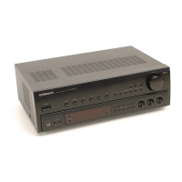
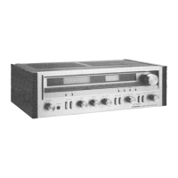
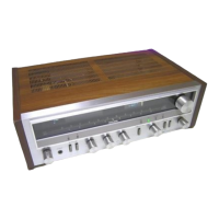
| Model | SX-3900 |
| Category | Stereo Receiver |
| Language | English |