Do you have a question about the Pioneer SX-3700 and is the answer not in the manual?
Details power output, distortion, and frequency response for the amplifier.
Covers sensitivity, selectivity, and signal-to-noise ratio for the AM tuner.
Specifies sensitivity, quieting, and signal-to-noise ratio for the FM tuner.
Lists power requirements, consumption, dimensions, and weight.
Lists items included with the unit, like operating instructions and antenna.
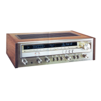
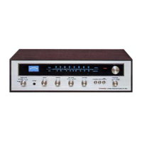
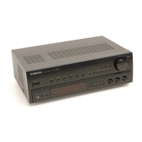
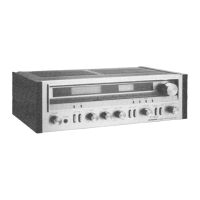
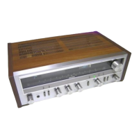
Describes key controls and indicators on the front panel.
Details bass, treble, low filter, tape monitor, function, balance, mode, loudness, and volume controls.
Illustrates the signal path of the RF receiver section.
Shows the signal flow of the audio frequency processing section.
Explains the FM front end, IF amplifier, detector, and multiplex decoder.
Describes the frequency servocontrol system for stable tuning.
Details the components and operation of the AM tuner stage.
Explains the frequency display and its components like FL tubes.
Explains the function and operation of the tuning indicators.
Describes the 5-point signal indicator display and its driver.
Details the electronic circuit that drives the tuning indicators.
Explains the circuit for the signal strength indicator.
Describes the equalizer amplifier IC and its specifications.
Explains the tone control amplifier circuit.
Details the power amplifier stages and output specifications.
Explains the circuit responsible for the output power indicators.
Describes the circuit protecting the amplifier and speakers.
Explains the circuit for detecting overload conditions.
Describes the circuit for detecting DC voltage at the output.
Provides instructions for removing the top cover of the unit.
Provides instructions for removing the bottom panel.
Provides instructions for removing the front panel assembly.
Identifies components and controls on the front panel.
Identifies internal components visible from the front.
Identifies components and connectors on the rear panel.
Shows the location of major internal assemblies.
Step-by-step instructions for threading the tuning dial cord.
Details FM tuner alignment procedures for optimal performance.
Explains adjustments for the multiplex decoder circuit.
Details AM tuner alignment procedures for optimal performance.
Describes how to set the amplifier's idle current.
Explains calibration for the frequency display circuit.
Details calibrating the output power indicators.
Shows the physical appearance of common semiconductor components.
Provides the main circuit schematic for the receiver.
Shows component placement and connections on PCBs.
Lists miscellaneous parts like assemblies and switches.
Lists transformers, antennas, and lamps.
Lists capacitor part numbers and symbols.
Lists additional capacitor part numbers and symbols.
Lists resistor part numbers and symbols.
Lists semiconductor part numbers and symbols.
Lists terminals, screws, and resonators.
Lists transformer part numbers and symbols.
Lists more semiconductor part numbers.
Lists coil part numbers.
Lists more capacitor part numbers.
Lists more resistor part numbers.
Lists more semiconductor part numbers.
Lists parts for the FL assembly.
Lists more semiconductor part numbers.
Lists more resistor part numbers.
Lists more semiconductor part numbers.
Lists items included in the package and general packing advice.
Shows an exploded view of external parts.
Lists part numbers for external components.
Lists part numbers for internal components.
| Power Output | 45 watts per channel into 8Ω (stereo) |
|---|---|
| Total Harmonic Distortion | 0.05% |
| Tuning Range | FM, MW |
| Damping Factor | 30 |
| Input Sensitivity | 2.5mV (MM), 150mV (line) |
| Output | 150mV (line) |
| Speaker Load Impedance | 4Ω to 16Ω |
| Semiconductors | 4 x IC |