Do you have a question about the Pioneer SX-939 and is the answer not in the manual?
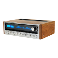
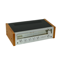
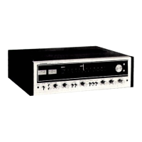
Controls for connecting speaker systems A, B, and C.
Jacks for connecting two pairs of headphones.
Controls for adjusting bass tone quality at 100Hz and 50Hz.
Buttons to reduce low-frequency rumble or high-frequency scratch.
Switch to enable flat frequency response regardless of tone controls.
Controls for adjusting treble tone quality at 10kHz and 20kHz.
Button to mute audio input by -20dB without turning volume down.
Switch for tape duplication or editing between two tape decks.
Meter for AM and FM station tuning.
Fine adjustment meter for FM reception.
Indicator for FM stereo reception.
Knob used for tuning AM and FM stations.
Buttons to select program source (AM, FM, PHONO, AUX).
Switch to turn the unit on and off.
Switch to adjust the brightness of indicator lights.
Button to suppress inter-station noise during FM tuning.
Button to compensate for hearing response at low volumes.
Jacks for connecting microphones.
Control for overall sound volume for speakers and headphones.
Button to select between STEREO and MONO playback.
Describes the signal flow through the unit.
Alignment procedures for the FM section in English.
Alignment procedures for the FM Multiplex section.
Alignment procedures for the AM section.
Alignment procedures for the power amplifier section.
Circuit connection diagram and a list of miscellaneous parts.
Schematic and PCB layout for the Tuner Assembly.
Schematic and PCB layout for the Muting Circuit Assembly.
Schematic and PCB layout for the Equalizer Amplifier Assembly.
Schematic and PCB layout for the Control Amplifier Assembly.
Schematic and PCB layout for the Power Amplifier Assembly.
Schematic and PCB layout for the Protection Circuit Assembly.
Schematic and PCB layout for the Power Supply Circuit Assembly.
Schematic and PCB layout for the Speaker Switch Circuit Assembly.
Schematic and PCB layout for the Mode/Loudness Switch Circuit Assembly.
Schematic and PCB layout for the Filter/Muting Switch Circuit Assembly.
Schematic and PCB layout for the Function/Monitor Switch Circuit Assembly.
Schematic and PCB layout for the Dimmer/FM Muting Switch Circuit Assembly.
Schematic and PCB layout for the Function Selector Switch Circuit Assembly.
Schematic and PCB layout for the 5P Connector Assembly.
Circuit connection diagram and miscellaneous parts for the 220V model.
Schematic and PCB layout for the 220V Power Supply Circuit Assembly.
| Tuning Range | FM, MW |
|---|---|
| Damping Factor | 30 |
| Input Sensitivity | 2.5 mV (MM), 150 mV (line) |
| Output | 150 mV (line) |
| Frequency Response | 10Hz to 30 kHz |
| Total Harmonic Distortion | 0.3% |
| Signal to Noise Ratio | 90dB (line) |
| Speaker Load Impedance | 4 ohms to 16 ohms |
| Semiconductors | 4 x IC |