Do you have a question about the Pioneer SX-650 and is the answer not in the manual?
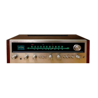
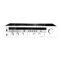
Details operation of volume, bass, treble, balance, loudness, and function selector controls.
Describes the power indicator lamp and stereo indicator lamp.
Explains functionality of high filter, FM muting, mode, and tape monitor switches.
Illustrates rear panel connections and top view of accessory AC outlets.
Explains AM/FM tuner, IF amplifier, and multiplex decoder operations.
Details phono equalizer, microphone, tone control, and power amplifier stages.
Covers the protection circuit and the power supply system.
Overview of the receiver's functional blocks from antenna to output.
Depicts signal level changes (dB) through amplifier stages.
Step-by-step guide for removing top cover, bottom plate, and front panel.
Instructions for properly stringing the tuning dial cord.
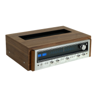
Identifies parts on front, rear, top, and bottom panels.
Procedures for tuning and aligning AM, FM, and MPX sections.
Shows exploded views of exterior parts and the main chassis.
Exploded views of tuner, amplifier, power supply, and rear panel assemblies.
Lists all parts for various assemblies including semiconductors, resistors, and capacitors.
Detailed schematics for key assemblies like Tuner, Amplifier, and Power Supply.
Lists all materials and steps for packing the unit.
| Power Output | 35 watts per channel into 8Ω (stereo) |
|---|---|
| Frequency Response | 20Hz to 20kHz |
| Tuning Range | FM, MW |
| Speaker Load Impedance | 4Ω to 16Ω |
| Total Harmonic Distortion | 0.3% |
| Input Sensitivity | 2.5mV (MM), 150mV (line) |
| Output | 150mV (line) |
| Dimensions | 480 x 149 x 349 mm |