Do you have a question about the Pioneer SX-950 and is the answer not in the manual?
Instructions for adjusting the voltage selector plug to match local mains supply.
Guidelines for using tape decks, including maintenance and proper placement for optimal performance.
Recommendations for turntable placement and record storage to protect from vibrations and dust.
Advice on speaker placement for optimal sound quality and vibration isolation.
Notes on how furniture materials can affect audio tone and sound reproduction quality.
Information on carpet's role in absorbing sound and vibrations for better acoustics.
Dual gate MOS FETs in the FM front end provide superior sensitivity and overload resistance.
Ceramic filters and IC limiters ensure stable operation and sharp selectivity in IF stages.
Quadrature detector and PLL circuit for clear FM separation and minimal distortion.
AM tuner circuit with AGC and ICs for improved selectivity and reduced distortion.
Robust power supply with large capacitors and protection for equipment safety.
Accurate RIAA equalization for phono inputs ensuring wide dynamic range.
Relay circuit safeguards transistors and speakers from DC voltage or overload.
Precise tone controls with selectable turnover frequencies and tone bypass for flexible audio adjustment.
85W per channel amplifier with direct coupling and low harmonic distortion.
Includes dual tape monitors, microphone input, and audio muting for enhanced versatility.
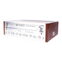
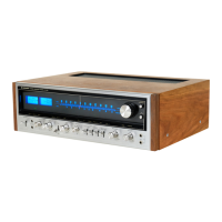
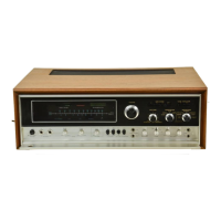
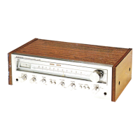
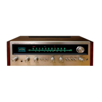
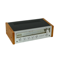
Elegant design featuring an aluminum front panel trimmed with solid walnut.
Diagram illustrating the connection of an outdoor FM antenna to the receiver.
Diagram showing the setup for connecting a T-type FM antenna.
Diagram detailing connections for indoor or outdoor AM antennas.
Schematic showing how to connect turntables to the receiver's PHONO inputs.
Diagram illustrating the connection of a cartridge tape player.
Explanation of PRE OUT and POWER IN jacks and their connecting plugs for amplifier configurations.
Diagram showing the connection of Speaker System A to the receiver's outputs.
Warning regarding the 240V mains supply voltage setting for use in the United Kingdom.
Details the wire colour code (Green-Yellow, Blue, Brown) for safe mains lead connections.
Instructions for connecting speaker systems to terminals A, B, C, ensuring correct polarity and impedance.
Guide for connecting turntables to PHONO 1 and PHONO 2 jacks, including ground wire.
Explanation of how to connect and utilize auxiliary audio components via the AUX input jacks.
Step-by-step guide on preparing speaker lead wires and connecting them securely to terminals.
Guidance on connecting FM antennas, covering outdoor and T-type options for optimal reception.
Instructions for connecting AM antennas, including ferrite bar and indoor/outdoor types.
Explanation of connecting the GND terminal to an earth ground for safety and noise reduction.
Explains the function of speaker system selection buttons (A, B, C) and their combinations.
Describes the stereo headphone output jack for private listening.
Notes the delay before sound output due to the protection circuit activation.
How the bass control affects low frequencies relative to the turnover switch setting.
Allows selection of bass turnover frequency (400Hz or 200Hz) for tone adjustment.
Explains the tone switch for engaging or bypassing tone controls for a flat frequency response.
Allows selection of treble turnover frequency (2.5kHz or 5kHz) for tone adjustment.
How the treble control affects high frequencies relative to the turnover switch setting.
Describes the FM tuning meter for accurately tuning radio stations.
How to use the signal meter for optimizing AM and FM station tuning.
Attenuates low-frequency rumble and noise below 30Hz.
Attenuates high-frequency scratch noise and hiss above 6kHz.
Eliminates FM stereo hiss, potentially reducing separation slightly.
Visual display indicating the currently selected audio source.
Buttons used to select the audio input source (AM, FM, PHONO, AUX).
Standard 6mm jack for connecting a microphone.
Reduces audio output by 20dB temporarily without altering volume control.
Controls the overall sound output level for speakers and headphones.
Enhances bass and treble at low volumes to compensate for hearing perception.
Allows selection between STEREO and MONO playback modes.
Adjusts the sound balance between left and right audio channels.
Activates external adaptor components like equalizers or Dolby units.
Enables tape playback monitoring through selected tape jacks.
Allows duplicating or editing tapes between two connected tape decks.
Suppresses interstation noise during FM tuning; can be disabled for weak signals.
Initial setup of various controls before powering on the receiver for safe operation.
Step-by-step instructions for tuning and optimizing FM radio reception.
Step-by-step instructions for tuning and optimizing AM radio reception.
How to connect and play external audio sources via the receiver's AUX input jacks.
Instructions for connecting and using a microphone with the receiver.
Explains the protection circuit's function and troubleshooting for extended silence or clicks.
Details the function of bass and treble turnover switches for adjusting frequency response.
Guides on connecting tape decks to the receiver's REC/PLAY and DIN jacks for recording and playback.
How to connect tape decks for recording using the receiver's output jacks.
How to connect tape decks for playback using the receiver's input jacks.
Steps for playing back tapes using TAPE MONITOR or ADAPTOR switches.
How to record audio from selected sources to tape decks via receiver output jacks.
Instructions for copying tapes using two tape decks and the TAPE DUPLICATE switch.
How to use a Dolby adaptor for FM broadcasts and tape recording/playback.
Steps to receive Dolby system FM broadcasts using the connected adaptor.
Information on connecting other adaptors like graphic equalizers via REC/PLAY jacks.
Connecting Dolby adaptor output to tape deck input jacks for recording.
Connecting tape deck output jacks to Dolby adaptor input for playback.
Steps to connect and operate a 4-channel system using the receiver and adaptors.
Guide on optimal speaker placement for 4-channel systems (front and rear configurations).
How to use a 4-channel FM broadcast adaptor for discrete FM reception.
How to use PRE OUT and POWER IN jacks to separate pre-amplifier and power amplifier sections.
Using the pre-amplifier section alone to drive an external power amplifier.
Connecting crossover networks and multiple amplifiers for advanced multi-way audio systems.
Troubleshooting noise issues encountered when listening to radio broadcasts.
Troubleshooting noise and howling issues during record playback.
Troubleshooting noise and feedback issues when using the microphone.
Lists the types and quantities of semiconductors (FETs, ICs, Transistors, Diodes) used.
Details power output, distortion, and frequency response of the power amplifier section.
Lists input sensitivities, impedance, overload levels, and output characteristics.
Provides specifications for FM reception: sensitivity, selectivity, and stereo separation.
Provides specifications for AM reception: sensitivity and selectivity.
Further details on AM section performance specifications.
Includes power requirements, dimensions, weight, and furnished parts.
Explains the accessory hex wrench for tuning knob adjustments and setscrew tightening.
| Total Harmonic Distortion | 0.1% |
|---|---|
| Tuning Range | FM, MW |
| Damping Factor | 30 |
| Input Sensitivity | 2.5mV (MM), 150mV (line) |
| Speaker Load Impedance | 4Ω to 16Ω |
| Type | Stereo Receiver |
| Year | 1976 |
| Signal to Noise Ratio | 95dB (line) |
| Power Output | 85 watts per channel into 8Ω (stereo) |