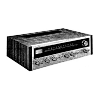
Do you have a question about the Pioneer SX-626 KCW and is the answer not in the manual?
| Tuning Range | FM, MW |
|---|---|
| Power Output | 27 watts per channel into 8Ω (stereo) |
| Frequency Response | 20Hz to 20kHz |
| Signal to Noise Ratio | 70 dB (MM) |
| Speaker Load Impedance | 4Ω to 16Ω |
| Dimensions | 432 x 140 x 347mm |
| Semiconductors | Transistors: 48, Diodes: 28, ICs: 2 |
Details on Bass, Treble, Volume, Loudness, Filter, Muting, Tape Monitor, and Selector controls.
Explanation of Signal Meter and Stereo Indicator functionality.
Information on Speaker, Phone, Mic jacks, and Tuning Knob usage.
Diagram showing component placement on the top side of the unit.
Diagram showing component placement on the bottom side of the unit.
List of necessary test equipment for performing unit alignment.
Step-by-step guide for adjusting AM reception and tracking.
Step-by-step guide for adjusting FM reception, tracking, and MPX.
List of components from the exploded view with part numbers.
Continuation of the component list with part numbers and model applicability.
Further listing of components, including part numbers and model variations.
Visual representation of unit assembly with numbered parts for identification.
Overall circuit diagram showing system interconnections and miscellaneous parts.
Schematics and parts list for the Tuner Assembly.
Schematics and parts list for the Equalizer Amplifier Assembly.
Schematics and parts list for the Control Amplifier Assembly.
Schematics and parts list for the Power Amplifier Assembly.
Schematics and parts list for the Power Supply Circuit Assembly.
Schematic and parts list for the Switch Circuit Assembly.
Schematic and parts list for the second Switch Circuit Assembly.
Schematic and parts list for the CR & Meter Drive Assembly.
 Loading...