Do you have a question about the Pioneer SX-626 Series and is the answer not in the manual?
| Power Output | 27 watts per channel into 8Ω (stereo) |
|---|---|
| Frequency Response | 20Hz to 20kHz |
| Total Harmonic Distortion | 0.8% |
| Signal to Noise Ratio | 70dB (MM), 90dB (line) |
| Tuning Range | FM, MW |
| Speaker Load Impedance | 4Ω to 16Ω |
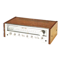
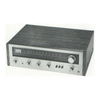
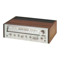
| Year | 1972 |
| Channel Separation | 45dB |
| Semiconductors | Transistors |
Configures input sources and speaker outputs.
Details antenna input and FM/AM tuner unit interface.
Outlines power supply connections and fuses.
Covers RF amplification and oscillator circuits in the FM front end.
Details the intermediate frequency output stage.
Describes the resistance network for input signals.
Details voltage regulation and filtering components.
Covers RF amplification and mixing in the tuner.
Details IF amplification and signal detection.
Describes multiplex and signal meter circuitry.
Covers input amplification and tone control circuits.
Details loudness function and output stages.
Details input selection and filter circuits.
Describes volume and balance control circuits.
Covers tape monitor and loudness switching functions.
Details filter and muting operations.
Describes initial amplification circuits.
Details the final power amplification stages.
Covers output protection and bias circuits.