EasyManua.ls Logo

Pioneer SX-300 Service Manual

Pioneer SX-300
34 pages
To Next Page IconTo Next Page
Page #1 background imageLoading...
Page #1 background image
<ART-026-0>
AM,/FM
STEREO RECEIVER
six-30cI
SOUND
PROJECT
BY
PIONEER
MODEL3OO
NOTE:
FVW,
NBW
KUW. KCW
THE
SX-3OO
AND
THE
MODEL
3OO
COME IN
TWO VERSIONS EACH DIS-
TINGUISHED
AS FOLLOWS:
Round label on
rear
panel
Voltage
Type
sx-300
Model
300
FVW
NBW
KUW
KCW
5-position
selector
220V
only
120V
only
120V
only
General
export model
SEMCO
(Sweden),
NEMCO
(Norway)
and
DEMCO
(Denmark)
approved
UL
approved
(U.S.A.)
CSA
approved
(Canada)
<73102Y31
L>
()rJroNEER'
Question and Answer IconNeed help?

Do you have a question about the Pioneer SX-300 and is the answer not in the manual?

Pioneer SX-300 Specifications

General IconGeneral
Power output15 watts per channel into 8Ω (stereo)
Frequency response20Hz to 20kHz
Input sensitivity2.5mV (MM), 150mV (line)
Output150mV (line)
Speaker load impedance4Ω to 16Ω
Signal to noise ratio70dB (MM)
Semiconductors1 x IC, 12 x transistors, 10 x diodes

Summary

Specifications

Front Panel Controls Overview

Speaker Selector and Power Switch

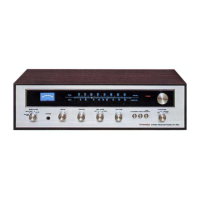
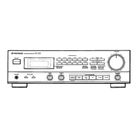
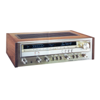
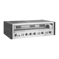
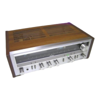
Controls speaker output selection and the unit's power state.

Tuning Knob and Signal Meter

Facilitates tuning and indicates signal strength.

Stereo Indicator

Indicates stereo reception status.

Front Panel Audio and Input Controls

Volume, Tone, and Balance Adjustment

Adjusts volume, bass, treble, and speaker balance.

Mode, Loudness, and Function Selection

Controls sound mode, loudness, and input source.

Tape Monitor and Headphone Jack

Features for tape monitoring and headphone connection.

Connection Diagram

Disassembly Procedure

Parts and P.C. Board Layout

Dial Cord Stringing Instructions

Alignment Procedures

FM/AM IF Alignment

Adjusts Intermediate Frequency circuits for FM and AM.

FM/AM Tracking Alignment

Aligns FM/AM circuits for accurate frequency tracking.

MPX Decoder Alignment

Calibrates the Multiplex (MPX) decoder circuit.

Other Alignment Procedures

Covers additional alignment steps like SCA filter and stereo indicator.

Level Diagram

Block Diagram

Exploded View and Parts List

Exploded View Diagram

Visual representation of component assembly.

Parts List

Detailed listing of all components and their part numbers.

Schematics and Circuit Diagrams

Circuit Connection and Parts

Overall circuit connection and miscellaneous component list.

AF Amplifier Assembly Schematics

Detailed schematics for the Audio Frequency amplifier.

Power Switch Circuit Assembly (FVW Model)

Schematics for the power switch circuit (FVW model).

Power Switch Circuit Assembly (NBW Model)

Schematics for the power switch circuit (NBW model).

Power Switch Circuit Assembly (KUW/KCW Models)

Schematics for the power switch circuit (KUW/KCW models).

Tuner Assembly Schematics

Detailed schematics for the tuner assembly.

Packing Method and Parts List

Related product manuals