Do you have a question about the Pioneer VSA-805S and is the answer not in the manual?
Procedure for removing the PS & FUNC assembly.
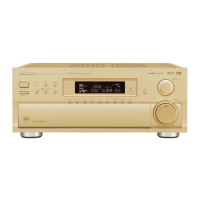
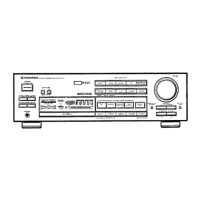
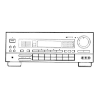
Details the exterior components and their relationships.
Instructions for disassembling and handling the power block.
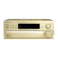
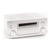
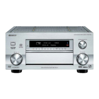
Describes how the product is packed and differences between models.
Schematics and connection diagrams for tuner and overall assemblies.
Schematic diagrams for the PS & FUNC assembly, part 1.
Schematics for headphone, speaker, and regulator assemblies.
Schematics for the FL & UCOM assembly.
Schematics for amplifier and 120W amplifier assemblies.
Schematics for the trans and volume control assemblies.
Pinout and function details for the PDG174A system microcomputer.
Diagram showing the grid assignment for the FL tube.
Table detailing anode connections for FL tube pins.
Pin assignment diagram for the FL tube and its connections.
Detailed pin connection table for the FL tube.
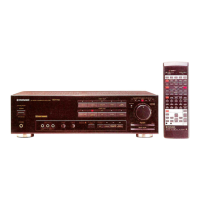
Exploded view and parts list for the remote control unit.
Diagram of the printed circuit board layout for the remote control.
| power requirements | 220 — 230 Volts, 50/60 Hz |
|---|---|
| power consumption | 700 W |
| standby power consumption | 3 W |
| continuous power output (DIN, 2 channels driven, 1 kHz, T.H.D. 1%, 4 Ω) | 120 W + 120 W |
|---|---|
| continuous power output (DIN, 2 channels driven, 20 Hz — 20,000 Hz, T.H.D. 0.09 %, 8 Ω) | 75 W + 75 W |
| total harmonic distortion (both channels driven, 20 Hz — 20,000 Hz, 8 Ω, 75 W output) | 0.09 % |
| phono input (sensitivity/impedance) | 2.8 mV/47 kΩ |
|---|---|
| cd input (sensitivity/impedance) | 200 mV/47 kΩ |
| vcr/tape 1 out, tape 2 rec (level/impedance) | 200 mV/2.2 kΩ |
| dimensions | 420 (W) x 162 (H) x 300 (D) mm |
|---|---|
| weight | 9.6 kg |