Do you have a question about the Pioneer VSA-E08 and is the answer not in the manual?
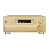
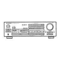
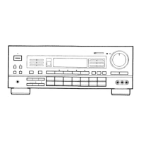
Visual breakdown of unit components.
Schematic for Main Control assembly.
Procedure for changing the unit's voltage input.
Schematics for input and connection assemblies.
First part of the main control unit schematic.
Second part of the main control unit schematic.
Third part of the main control unit schematic.
First part of the V-AMP assembly schematic.
Schematic for the main channel limiter circuit.
| Type | AV Receiver |
|---|---|
| Frequency Response | 5 Hz - 100 kHz |
| Total Harmonic Distortion (THD) | 0.08% |
| Input Sensitivity | 200 mV |
| Signal-to-Noise Ratio | 100 dB |
| Speaker load impedance | 6Ω to 16Ω |
| Digital inputs | coaxial, optical |
| Video inputs | No |