VSA-E08
9
A
B
C
D
1
234
1
2
3
4
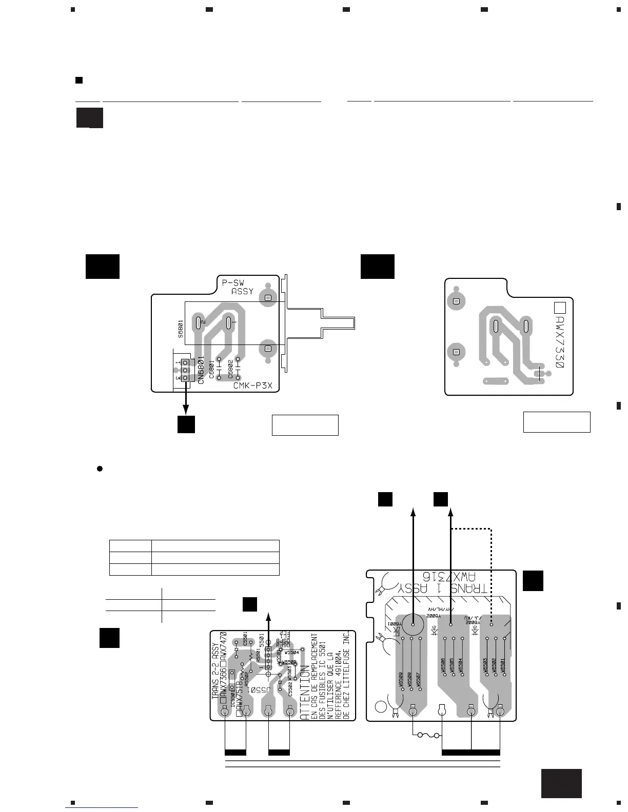
2. PCB CONNECTION DIAGRAM
2.1 P-SW ASSY
PCB PARTS LIST
Mark No. Description Part No.
P-SW ASSY
SWITCHES AND RELAYS
S6801 ASG1035
(ANP7308-F)
(ANP7308-F)
220-230V
240V
T1
POWER
TRANSFORMER
(ANP7010-D)
(ANP7010-D)
J6000
V
P-SW ASSY
V A
P-SW ASSY
V A
SIDE A
SIDE B
Line Voltage can be changed by the following modification:
1. Disconnect the AC power cord.
2. Remove the cover.
3. Change the connection wire from TRANS 1 ASSY
(Terminal No. Y6002) to AMP ASSY (Terminal No. Y6002)
as follows.
Voltage Terminal No. of TRANS 1 ASSY
220-230V Y6002/HY/HL/HV
240V Y6002/J,/KU
4. Stick a line voltage label on the rear panel.
Description Part No.
220V label AAX-193
240V label AAX-192
Line Voltage Selection
Y6001
V
TRANS 2-2
ASSY
O
TRANS 1
ASSY
N
5009
M
Y6002
V
V
A
V A
CAPACITORS
C6801, C6802 CGCYX103K25
OTHERS
CN6801 3P JUMPER CONNECTOR 52151-0310
Mark No. Description Part No.