ORDER NO.
PIONEER CORPORATION 1-1, Shin-ogura, Saiwai-ku, Kawasaki-shi, Kanagawa 212-0031, Japan
PIONEER ELECTRONICS (USA) INC. P.O. Box 1760, Long Beach, CA 90801-1760, U.S.A.
PIONEER EUROPE NV Haven 1087, Keetberglaan 1, 9120 Melsele, Belgium
PIONEER ELECTRONICS ASIACENTRE PTE. LTD. 253 Alexandra Road, #04-01, Singapore 159936
PIONEER CORPORATION
2010 Printed in Japan
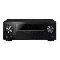
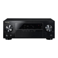
VSX-31
RRV4079
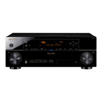
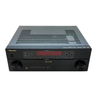
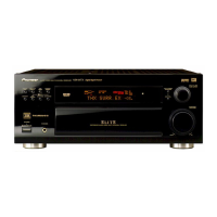
AUDIO/VIDEO MULTI-CHANNEL RECEIVER
VSX-31
VSX-30
VSX-925-K
THIS MANUAL IS APPLICABLE TO THE FOLLOWING MODEL(S) AND TYPE(S).
This service manual should be used together with the following manual(s).
For SPECIFICATIONS and PANEL FACILITIES, refer to the operating instructions.
Model Type Porew Requirement Remarks
VSX-31 UXCNCB AC 120 V
VSX-30 UXCNCB AC 120 V
VSX-925-K CUXCN AC 120 V
Model No. Order No. Remarks
VSX-1020-K/UXCNCB RRV4045
K-ZZZ MAY
w
w
w
.
x
i
a
o
y
u
1
6
3
.
c
o
m
Q
Q
3
7
6
3
1
5
1
5
0
9
9
2
8
9
4
2
9
8
T
E
L
1
3
9
4
2
2
9
6
5
1
3
9
9
2
8
9
4
2
9
8
0
5
1
5
1
3
6
7
3
Q
Q
TEL 13942296513 QQ 376315150 892498299
TEL 13942296513 QQ 376315150 892498299
http://www.xiaoyu163.com
http://www.xiaoyu163.com