Do you have a question about the Pioneer VSX-39TX and is the answer not in the manual?
Checks for customer and technician protection, including leakage current.
Special safety characteristics of electrical and mechanical parts.
Exploded view and parts list for packing components.
Exploded view of external parts and their placement.
List of exterior components with part numbers.
Compares parts across different models for consistency.
Exploded view and parts list for the heat sink assembly.
Exploded view of the front panel components.
Detailed list of parts for the front panel section.
Comparison of parts for different models on the front panel.
High-level functional overview of the receiver's circuitry.
Visual representation of how all internal components are connected.
Wiring diagrams for specific input/connection assemblies.
Detailed schematic for the main control assembly.
Schematic diagram for the main control assembly, part 2.
Schematic diagram for the main control assembly, part 3.
Schematic for the Voltage Amplifier assembly, part 1.
Schematic for the Voltage Amplifier assembly, part 2.
Schematics for amplifier and terminal assemblies.
Schematics for transistor, diode, and power supply/speaker assemblies.
Schematics for regulator and transistor assemblies.
Schematics for video and S-video input assemblies.
Schematics for headphone, display, encoder, and volume assemblies.
Schematic diagram for the primary assembly.
Schematics for RF, digital input, and optical output assemblies.
Schematic diagram for the Digital Signal Processor assembly, part 1.
Schematic diagram for the Digital Signal Processor assembly, part 2.
Schematic diagram for the Digital Signal Processor assembly, part 3.
Schematic diagram for the Digital Signal Processor assembly, part 4.
Schematic diagram for the Digital Signal Processor assembly, part 5.
Schematics for 2-channel I/O and trim assemblies.
Schematic diagram for the component assembly.
Explains symbols and conventions used in PCB diagrams.
PCB layout for the main control assembly.
PCB layout for the voltage amplifier assembly.
PCB layouts for various amplifier and terminal assemblies.
PCB layouts for transistor, diode, and power assemblies.
PCB layout for the speaker/power supply assembly.
PCB layouts for regulator and primary assemblies.
PCB layouts for video assemblies.
PCB layouts for S-Video assemblies.
PCB layouts for headphone, display, encoder, and volume assemblies.
PCB layout for the Digital Signal Processor assembly.
PCB layouts for RF, optical, and component assemblies.
PCB layouts for 2-channel I/O and trim assemblies.
Explains part marking and resistor coding for PCB parts.
Comprehensive list of all PCB assemblies and their part numbers.
Compares PCB assemblies across different models.
Procedure for adjusting idle current on various channels.
Step-by-step guide for disassembling the unit's main sections.
Pin assignments and functions for integrated circuits.
Grid and pin assignment for the display unit.
Exploded views and parts list for the remote control.
Schematic diagram for the remote control's main PCB.
PCB layout diagram for the remote control.
Exploded views and parts list for remote controls 37 and 909S.
PCB layout diagrams for remote controls 37 and 909S.
Schematic diagram for remote controls 37 and 909S.
Parts list for PCB diagrams of remote controls.
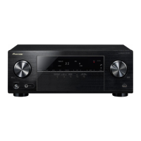
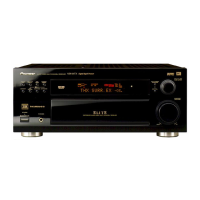
Explanation and illustration of front panel controls and indicators.
Detailed explanation of front panel controls for VSX-39TX.
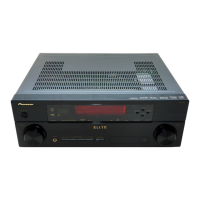
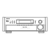
Detailed explanation of front panel controls for VSX-D909S.
Detailed explanation of front panel controls for VSX-37TX/VSX-36TX/VSX-D909S.
Explanation of various indicators on the receiver's display.
Detailed explanation of buttons on the VSX-39TX remote control.
Explanation of the receiver's main LCD screen functions.
Explanation of the receiver's sub LCD screen functions.
Explanation of buttons on the VSX-37TX/VSX-36TX/VSX-D909S remote control.
Technical specifications for the audio output and input sections.
Technical specifications for video input and output.
Technical specifications for the FM tuner.
Technical specifications for the AM tuner.
General specifications including power and dimensions.
List of parts included with the unit.
Guidelines for cleaning and maintaining the unit's exterior.
Technical specifications specific to the VSX-37TX model.
Technical specifications specific to the VSX-36TX model.
List of included accessories for the VSX-39TX model.
List of included accessories for VSX-37TX/36TX/D909S models.