Do you have a question about the Pioneer VSX-D909S and is the answer not in the manual?
| Channels | 5.1 |
|---|---|
| Total Harmonic Distortion | 0.09% |
| Input Impedance | 47 kΩ |
| Input Sensitivity | 200 mV |
| Signal to Noise Ratio | 100 dB |
| Video Connections | Composite, S-Video |
| Speaker load impedance | 8 ohms |
| Digital inputs | Optical, Coaxial |
| Power Output | 100W per channel (8 ohms, 20Hz-20kHz, 0.09% THD) |
Check for customer and service technician protection.
Special safety characteristics of electrical/mechanical parts.
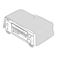
Details on how the receiver is packed for shipment.
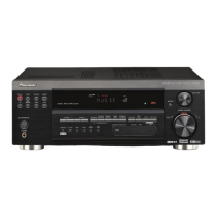
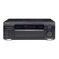
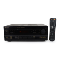
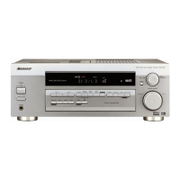
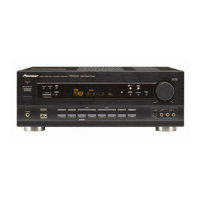
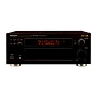
Illustrations showing the external components and their layout.
Diagrams and parts list for the heat sink assembly.
Exploded view and parts list for the front panel components.
Overall block diagram of the receiver's signal flow.
Diagram showing the wiring connections between major assemblies.
Schematics for external input and connection board assemblies.
Part 1 of the schematic for the main control assembly.
Part 2 of the schematic for the main control assembly.
Part 3 of the schematic for the main control assembly.
Part 1 of the schematic for the V-AMP assembly.
Part 2 of the schematic for the V-AMP assembly.
Schematics for amplifier channel and terminal assemblies.
Schematics for power supply and related transistor/diode assemblies.
Schematics for voltage regulators and transistor assemblies.
Schematics for video input and S-Video input assemblies.
Schematics for front panel interface and control assemblies.
Schematic for the primary power supply assembly.
Schematics for RF/Digital input, optical output, and component assemblies.
Part 1 of the schematic for the Digital Signal Processor (DSP) assembly.
Part 2 of the schematic for the Digital Signal Processor (DSP) assembly.
Part 3 of the schematic for the Digital Signal Processor (DSP) assembly.
Part 4 of the schematic for the Digital Signal Processor (DSP) assembly.
Part 5 of the schematic for the Digital Signal Processor (DSP) assembly.
Schematics for 2-channel I/O and trim assemblies.
Schematic for the component assembly.
PCB connection diagrams for input and connector assemblies.
PCB connection diagram for the main control assembly.
PCB connection diagram for the V-AMP assembly.
PCB connection diagrams for amplifier channel and terminal assemblies.
PCB connection diagrams for power supply and transistor assemblies.
PCB connection diagram for the Speaker/Power Supply assembly.
PCB connection diagrams for regulator and primary power supply assemblies.
PCB connection diagrams for video input assemblies.
PCB connection diagrams for S-Video input assemblies.
PCB diagrams for front panel interface and control assemblies.
PCB connection diagram for the Digital Signal Processor (DSP) assembly.
PCB diagrams for RF/Digital, optical out, and component assemblies.
PCB diagrams for 2-channel I/O and trim assemblies.
List of part numbers for all PCB assemblies used in the receiver.
Comparison of PCB assemblies across different receiver models.
Specific PCB parts list for the VSX-39TX/KU/CA model.
Procedure for adjusting idle current on amplifier channels.
Step-by-step instructions for disassembling the receiver's main parts.
Diagram showing the location of PCBs within the front panel section.
Diagram showing the location of major internal assemblies.
List and pin assignment of Integrated Circuits (ICs).
Information about the display assembly, including FL indicator and grid assignment.
Button to switch the receiver ON or into STANDBY mode.
Press to switch the remote control into receiver mode.
Basic controls for switching receiver modes and controlling other components.
Screen for customizing remote control functions and settings.
Use to customize remote control functions and settings.
Use to lock the remote control to prevent accidental activation.
Buttons specifically for controlling TV functions like power and volume.
Press to select a source; cycles through all possible sources.
Use to raise or lower the receiver's volume.
Press to mute or restore the volume.
Turns off all PIONEER or programmed components.
Starts the MULTI OPERATION mode for programming and control.
Adjusts effect amount (DSP/Theater) and selects channels for adjustment.
Displays the main receiver interface, showing DSP, stereo, and effect modes.
Displays sub-receiver screen information, including input and mode selections.
Switches the remote between USE and SETUP modes.
Turns on other components after recalling or teaching signals.
Starts the MULTI OPERATION mode for programming and control.
Turns off all PIONEER or programmed components.
Press to turn the receiver power ON or to STANDBY.
Select a source and the corresponding remote operation mode.
Control specific components like CD or DVD players after programming.
Perform various functions depending on remote mode (CD, tuner).
Buttons used to control the TV functions only.
Use to raise or lower the receiver's volume.
Lowers analog signal input level to prevent distortion.
Customize remote control functions and settings.
Access various menus for TV or DTV.
Press to mute or restore the volume.
Adjusts effect amount (DSP/Theater) and selects channels for adjustment.
Set up speaker and sound systems for surround sound.
Press to select a source; cycles through all possible sources.
Operate on-screen menus for setup and input commands.
Switches the DIGITAL NR on or off.
Selects the input signal type (Analog, Digital, AC-3 RF, Auto).
Switches the MIDNIGHT mode on or off.
Connects external components for multi-channel input.
Press repeatedly to select a DSP sound mode.
Switches between STEREO, DIRECT, or other sound modes.
Press to light the remote control buttons.
Selects the desired surround sound mode (e.g., DTS).
Details power output, input sensitivity, frequency response, and tone controls.
Specifications for video input and output, signal-to-noise ratio, and frequency response.
Specs for component video input/output, S/N ratio, and frequency response.
Frequency range, sensitivity, S/N ratio, distortion, and selectivity for FM tuner.
Frequency range, sensitivity, selectivity, and S/N ratio for AM tuner.
Power requirements, consumption, dimensions, and weight of the unit.
List of accessories and parts included with the receiver.
Instructions for cleaning and maintaining the unit's exterior surfaces.
List of accessories included with the VSX-39TX model.
List of accessories included with VSX-37TX, VSX-36TX, VSX-D909S models.