Do you have a question about the Pioneer XC-F10 and is the answer not in the manual?
| Tuner Type | Digital |
|---|---|
| Number of Presets | 30 |
| Frequency Range FM | 87.5 - 108 MHz |
| CD Player | Yes |
| Sensitivity AM | 30 µV |
| Signal-to-Noise Ratio FM | 70 dB |
| Total Harmonic Distortion FM | 0.3% |
| Total Harmonic Distortion AM | 0.5% |
| Power Supply | AC 220-240V, 50/60Hz |
| Frequency Range AM | 522 kHz - 1611 kHz |
| Frequency Range MW | 531 - 1602 kHz |
Important warnings and instructions regarding the safe handling and replacement of lithium batteries.
Safety guidelines for avoiding exposure to laser radiation when the unit is open.
Details and part numbers for the packing materials used for the product.
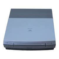
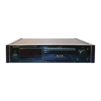
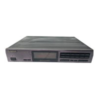
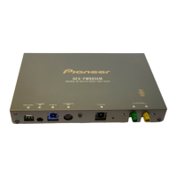
Identification of external parts and their corresponding part numbers.
An overview of the main functional blocks and their interconnections within the system.
Detailed circuit diagram for the FM/AM tuner section of the device.
Circuit diagram for the self-check CD assembly, detailing its components and connections.
Circuit diagrams for the main unit and auxiliary input sections of the device.
Detailed circuit diagrams for the second part of the main unit.
Circuit diagrams for various interface and control units including display, LEDs, keys, sensors, and CD switches.
Top and bottom view of the printed circuit board for the FM/AM tuner module.
Printed circuit board layouts for the main unit and auxiliary units.
PCB layouts for the display, LED, key, sensor, and CD switch units.
Printed circuit board layouts for the self-check CD assembly and motor unit.
List of major PCB assemblies with their model numbers.
Comprehensive list of components and their part numbers for the FM/AM tuner module.
Detailed list of components and part numbers for the self-check CD assembly.
List of all components and their corresponding part numbers for the main unit.
Component and part number list for the auxiliary unit.
Parts list for the display unit, including semiconductors, coils, capacitors, and resistors.
Component and part number list for the LED unit.
Parts list for the right key unit, including switches, relays, and resistors.
Components and part numbers for the left key unit, including switches and resistors.
List of semiconductors and other components for the sensor unit.
Parts list for the CD switch unit, including switches, relays, and resistors.
Components and part numbers for the motor unit, including capacitors and others.
Instructions for entering and operating the device in various test modes for adjustment.
Step-by-step guide on how to initiate and exit the service test mode.
Explanation of functions and operations specifically within the CD test mode.
Notes regarding adjustments for the AM tuner section, indicating no adjustments are needed.
Procedures and conditions for adjusting the FM tuner section, specifically the T-METER adjustment.
General diagnostic information and troubleshooting procedures for identifying issues.
Step-by-step guide on how to disassemble the unit for servicing.
Method for operating the unit in a single mode, often for testing or specific functions.
Detailed pin functions and information for integrated circuits used in the system.
Details on the FL display's anode connections and pin assignments.
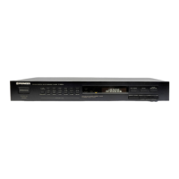
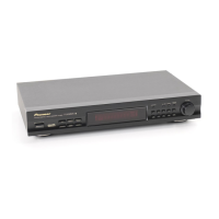
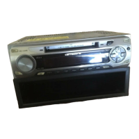
Identification and function of the buttons and indicators on the CD tuner's front panel.
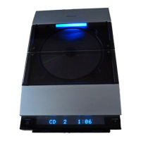
Explanation of the various indicators on the display and what they signify.
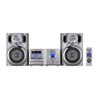
Technical specifications for the XC-F10 stereo CD tuner, including frequency ranges and dimensions.
List of accessories that come with the stereo CD tuner, like remote control and cables.