ORDER NO.
PIONEER ELECTRONIC CORPORATION 4-1, Meguro 1-Chome, Meguro-ku, Tokyo 153-8654, Japan
PIONEER ELECTRONICS SERVICE, INC. P.O. Box 1760, Long Beach, CA 90801-1760, U.S.A.
PIONEER ELECTRONIC (EUROPE) N.V. Haven 1087, Keetberglaan 1, 9120 Melsele, Belgium
PIONEER ELECTRONICS ASIACENTRE PTE. LTD. 501 Orchard Road, #10-00 Wheelock Place, Singapore 238880
PIONEER ELECTRONIC CORPORATION 1998
RRV2036
CONTENTS
T – ZZK OCT. 1998 Printed in Japan
1. SAFETY INFORMATION ...................................... 2
2. EXPLODED VIEWS AND PARTS LIST ................ 3
3. SCHEMATIC DIAGRAM ..................................... 14
4. PCB CONNECTION DIAGRAM .......................... 34
5. PCB PARTS LIST ............................................... 49
6. ADJUSTMENT .................................................... 55
7. GENERAL INFORMATION ............................... 61
7.1 PARTS ......................................................... 61
7.1.1 IC ......................................................... 61
7.1.2 DISPLAY.............................................. 73
7.2 DISASSEMBLY ........................................... 75
7.3 BLOCK DIAGRAM....................................... 78
8. PANEL FACILITIES AND SPECIFICATIONS .... 80
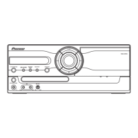
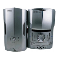
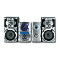
STEREO CD/VCD CASSETTE DECK RECEIVER
XR-VS99
THIS MANUAL IS APPLICABLE TO THE FOLLOWING MODEL(S) AND TYPE(S).
Type
Model
Power Requirement
The Voltage can be converted by
XR-VS99 the following method.
DBDXJ AC110-127V/220-230V/240V With the voltage selector
DLXJ/NC AC110-127V/220-230V/240V With the voltage selector
PREV NEXT RETURN SELECT