ORDER NO.
PIONEER CORPORATION 4-1, Meguro 1-chome, Meguro-ku, Tokyo 153-8654, Japan
PIONEER ELECTRONICS (USA) INC. P.O. Box 1760, Long Beach, CA 90801-1760, U.S.A.
PIONEER EUROPE NV Haven 1087, Keetberglaan 1, 9120 Melsele, Belgium
PIONEER ELECTRONICS ASIACENTRE PTE. LTD. 253 Alexandra Road, #04-01, Singapore 159936
PIONEER CORPORATION 2005
RRV3259
T – ZZK AUG. 2005 Printed in Japan
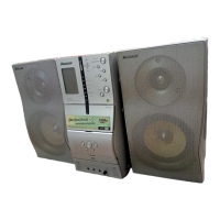
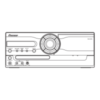
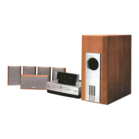
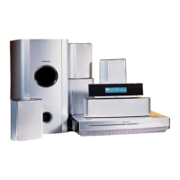
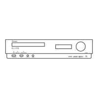
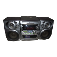
STEREO DVD CASSETTE DECK RECEIVER
XV-EV500
THIS MANUAL IS APPLICABLE TO THE FOLLOWING MODEL(S) AND TYPE(S).
Model No. Order No. Remarks
XV-EV500/DLXJ/NC RRV3216
¶ This service manual should be used together with the following manual(s):
For SPECIFICATIONS and PANEL FACILITIES, refer to the operating instructions.
Model Type Power Requirement Region No. Remarks
XV-EV500 DFXJ AC110V-127V/220-230V/240V 3
XV-EV500 DDXJ/RB AC110V-127V/220-230V/240V 2
XV-EV500 DTXJ AC110V-127V/220-230V/240V 3