S
Stephanie BartonSep 23, 2025
What does it mean when my Pioneer YH024GHFI18RT2 displays an abnormal AC voltage?
- FfevansSep 23, 2025
If your Pioneer Heat Pump is experiencing abnormal AC voltage (either >275V or
What does it mean when my Pioneer YH024GHFI18RT2 displays an abnormal AC voltage?
If your Pioneer Heat Pump is experiencing abnormal AC voltage (either >275V or
Why is my Pioneer Heat Pump not cooling or heating properly?
If your Pioneer Heat Pump isn't cooling or heating well, start by cleaning the outdoor unit's heat exchanger. Remove any indoor heating devices and maintain good air tightness in the room. Clear any blockages from the outdoor heat exchanger and double-check the temperature settings.
What to do if my Pioneer YH024GHFI18RT2 Heat Pump is leaking water?
If your Pioneer Heat Pump is leaking water, the drainage pipe may be blocked or broken. Try changing the drainage pipe. Also, check the refrigerant pipe joint's wrap to ensure it's completely sealed and re-wrap it tightly if necessary.
Why does the compressor in my Pioneer YH024GHFI18RT2 Heat Pump start and stop frequently?
If the compressor in your Pioneer Heat Pump starts and stops frequently, it might be due to blocked air inlet or outlet. Remove any obstacles that are causing the blockage.
How to fix a Pioneer YH024GHFI18RT2 that is lacking refrigerant?
If your Pioneer Heat Pump is low on refrigerant, discharge the existing refrigerant and then recharge it according to the rating label instructions.
What causes an EEprom Data error in a Pioneer YH024GHFI18RT2 Heat Pump?
To fix an EEprom Data error in your Pioneer Heat Pump, replace the EE components. If that doesn't work, replace the outdoor control board components or reassemble the EE components.
What should I do if my Pioneer YH024GHFI18RT2 displays a defrosting sensor fault?
If your Pioneer Heat Pump is showing a defrosting sensor fault, first, reconnect the wiring of the defrosting sensor. If the problem persists, replace the defrosting sensor or the outdoor control board.
How can I resolve an IPM and control board communication fault in my Pioneer YH024GHFI18RT2 Heat Pump?
To address an IPM and control board communication fault in your Pioneer Heat Pump, begin by reconnecting the cable between the control board and the driver board. If the issue persists, replace the communication cable between these boards, or replace the driver board or the control board.
How to fix a 4-way valve commutation failure in a Pioneer Heat Pump?
To resolve a 4-way valve commutation failure in your Pioneer Heat Pump, start by reconnecting the wiring of the 4-way valve. If the problem persists, replace the 4-way valve coil, the 4-way valve itself, or the driver board of the way valve.
Why does my Pioneer YH024GHFI18RT2 Heat Pump turn off due to high pressure protection?
If your Pioneer Heat Pump's high-pressure switch is activated, or the unit is shutting down due to high-pressure protection, begin by reconnecting the wiring of the high-pressure protector. If the problem continues, replace the high-pressure protector. A faulty outdoor control board could also be the cause, so consider replacing it. Overload in cooling or heating modes may also trigger this protection.
Details important notices, signal words (DANGER, WARNING, CAUTION), and their definitions.
Provides essential safety instructions for installation, operation, maintenance, and specific warnings.
Describes 360 DC inverter technology, pressure sensor, compact design, and user comfort features.
Lists available models, capacities, and their official model numbers.
Specifies working voltage, operating temperatures, and unit installation compatibility.
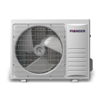
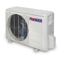
Visual representation of the outdoor units for different models.
Comprehensive data on cooling, heating, electrical, and refrigeration system parameters.
Details on compressor, refrigerant, piping, dimensions, weight, and test condition notes.
Detailed dimensional drawings and measurements for the 24K outdoor unit.
Detailed dimensional drawings and measurements for the 36K outdoor unit.
Detailed dimensional drawings and measurements for the 60K outdoor unit.
Information on applicable voltage, power supply, and Electric Leakage Breaker ratings.
Performance data for cooling operation at various ambient temperatures for 24K unit.
Performance data for heating operation at various ambient temperatures for 36K unit.
Factors to adjust capacity based on pipe length and height difference.
Correction factors for heating capacity considering defrosting periods.
Sound pressure level charts for 24K, 36K, and 60K outdoor units across frequency bands.
Illustrates the refrigerant cycle and lists components for the 24K outdoor unit.
Illustrates the refrigerant cycle and lists components for the 36K outdoor unit.
Illustrates the refrigerant cycle and lists components for the 60K outdoor unit.
Shows the electrical wiring diagram for the 24K outdoor unit.
Shows the electrical wiring diagram for the 36K outdoor unit.
Shows the electrical wiring diagram for the 60K outdoor unit.
Identifies components on main control and display boards for 24K unit.
Identifies components on driver and filter boards for 36K/60K units.
Provides recommended wire sizes for power source and transmitting cables based on model capacity.
Details DIP switch settings for 24K, 36K, and 60K outdoor units for various modes.
Explains how to query system parameters using the 7-segment display for 24K unit.
Lists parameter codes and their descriptions for checking system status.
Specifies maximum allowed pipe length and height difference between units.
Procedures for air tight testing and calculating additional refrigerant charge.
List of tools and instruments required for installation, including R410A specific items.
Outlines the sequence of installation steps from drawing audit to test run.
Describes control functions like protection modes, operation modes, and valve controls.
Resistance values for the discharge temperature sensor across a wide temperature range.
Resistance values for other sensors, covering a wide temperature range.
Guide for common issues like unit not starting, frequent stops, or poor performance.
Explains how fault codes are displayed using LEDs and 7-segment displays.
Lists outdoor unit fault codes, causes, and recommended solutions.
Details drive fault codes for 24K and 36K/60K units, their causes, and solutions.
Procedure and tools for checking the refrigerant system, including pressure and defrosting.
Instructions for checking the outdoor fan motor and compressor resistance and continuity.
Step-by-step guide for disassembling and assembling the outdoor unit components.
Explains the communication signals between indoor units, outdoor unit, and thermostat.
Details start, stop, and protection conditions for cooling mode operation.
Details start, stop, and protection conditions for heating mode operation.
Explains condenser high-temperature protection mechanisms in cooling and heating modes.
| Model Number | YH024GHFI18RT2 |
|---|---|
| Category | Heat Pump |
| Refrigerant | R410A |
| Heating Capacity | 24000 BTU |
| Cooling Capacity | 24000 BTU |
| Weight (Indoor Unit) | 9 kg |
| Weight (Outdoor Unit) | 35 kg |