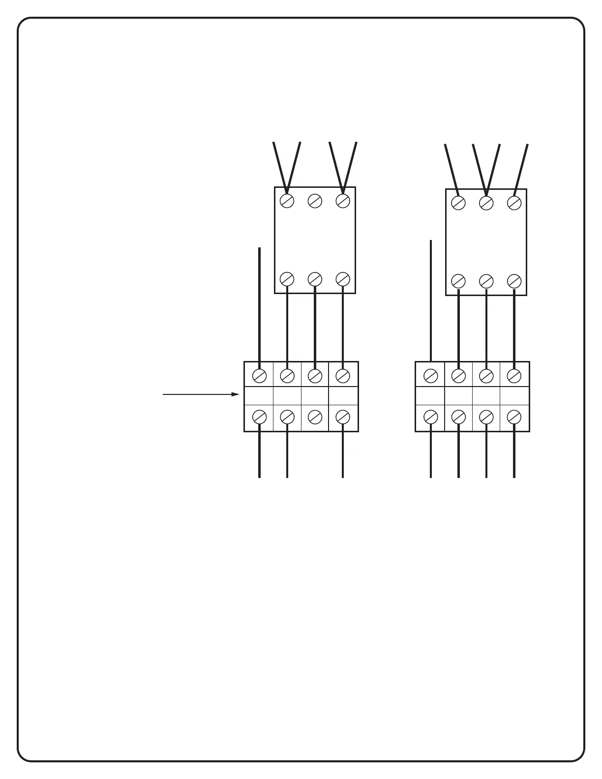
OP-3 PHASE CONVERSION
L1 L2 L3
T1 T2 T3
BACK VIEW OF
ON/OFF SWITCH
L1 L2 L3
T1 T2 T3
BACK VIEW OF
ON/OFF SWITCH
L1 L2 L3N L1 L2 L3N
WHITE
BLACK
RED
BLUE
WHITE
BLACK
RED
BLUE
NEUTRAL
HOT
HOT
NEUTRAL
HOT
HOT
HOT
SUPPLY CIRCUIT
1 PHASE
3 WIRE
SUPPLY CIRCUIT
3 PHASE
4 WIRE
Field wiring terminal block
Connect supply circuit as shown
If “HI LEG” is present,
connect to Terminal L2
Connect red wires on the
Load side of the oven on-off
switch as shown to match
supply circuit phase.
If more than one oven
switch is used in the unit,
wire connections must be
the same on all switches.
BLACK
BLACK
RED
RED
BLUE
BLUE
RED
RED
L2-L1
L2-L3
L2-L3
L2-L1
PHASE CONVERSION INSTRUCTION FOR UNITS USING A 3 POLE SWITCH TO TURN UNIT ON OR OFF
22