PIPER SENECA
II SERVICE MANUAL
SECTION
VIII
POWER PLANT
TURBOCHARGED
8-1. INTRODUCTION.
The purpose of this section is to provide instructions
for the removal. minor repair.
service
and installation of
the engine and components.
For instructions
on major repairs
and overhauls.
consult the appropriate publication of the component manufacturer.
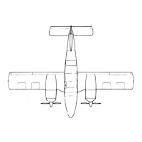
8-2. DESCRIPTION.
The PA-34-200T is powered by Teledyne Continental
turbocharged. overhead valve.
air
cooled. horizontally
opposed. direct
drive, wet sump engines
rated 200 hp
at sea level.
Each engine
is enclosed by
cowling consisting
of two
side panels. an
upper and lower
section and
a nose
section. The cowl flap
is an integral part of
the lower cowl and is operated
manually through
a push-pull cable
arrangement from the cockpit.
Propellers are
Hartzell full feathering.
constant speed each
controlled by a governor
mounted on the
engine supplying oil
through the propeller shaft
at various pressures.
Oil pressure from the
governor moves the
blades
into low pitch (high
RPM). The centrifugal
twisting moment of
the blade also tends to
move the blades
into low pitch. Opposing
these two forces
is a force produced
by a compressed air charge
between the cylinder
head and the piston
which tends to move the
blades into high pitch
in the absence of governor
oil pressure.
Thus. feathering is accomplished by compressed air.
Refer
to Section IX for description
of fuel system and primer operation.
8-2a. STANDARD
PRACTICES
- ENGINE.
The following
suggestions
should be applied
wherever
they
are needed
when working on
the power plant.
a.
To insure proper
reinstallation
and, or
assembly, tag
and mark all parts.
clips, and
brackets as to
their location
prior to their removal
and or disassembly.
b.
During removal
of various tubes
or engine
parts. inspect them
for indications
of scoring.
burning or
other
undesirable conditions. To facilitate reinstallation.
observe the location of each part during
removal.
Tag
any unserviceable
part and or
units for investigation
and possible
repair.
c.
Extreme care
must be taken
to prevent foreign
matter from
entering the
engine. such
as lockwire.
washers. nuts.
dirt. dust. etc. This
precaution applies whenever
work is done on
the engine. either on or
off the
aircraft.
Suitable protective
caps. plugs.
and covers must
be used to
protect all openings
as they are
exposed.
NOTE
Dust
caps used
to protect open
lines must always
be installed
OVER
the tube
ends and NOT IN the tube ends.
Flow through the lines may
be blocked off
if lines are inadvertently
installed
with dust
caps in the
tube ends.
d. Should
any items be
dropped into
the engine. the
assembly process
must stop and
the item removed.
even
though this may
require considerable
time and
labor. Insure
that all parts
are thoroughly
clean before
assembling.
c.
Never reuse
any lockwire.
lockwashers.
tablocks. tabwashers
or cotter
pins. All lockwire
and cotter
pins must fit
snugly in holes
drilled in studs
and bolts for
locking purposes.
Cotter pins
should be installed
so
the head
fits into the
castellation of
the nut. and unless
otherwise
specified. bend
one end of the
pin back over
the stud or bolt
and the other
end down flat
against the nut.
Use only corrosion
resistant steel
lockw ire and
or
cotter pins.
Bushing
plugs shall
be lockwired
to the assembly
base
or case. Do
not lockwire
the plug
to the
bushing.
f. All gaskets.
packings
and rubber
parts must
be replaced with
new items
of the same
type at
reassembly.
Insure
the new
nonmetallic
parts being
installed
show no sign
of having
deteriorated
in storage.
Revised:
8/10/80
2APOWER
PLANT
2A11
 Loading...