FLIGHT SWITCH
FAN
PIPER SENECA
II SERVICE
MANUAL
MASTER
SWITCH
AIR VALVE SWITCH
(SHOWN NOT CLOSED)
HEATER
DEFROST
VENT
BLOWER
FUEL
VALVE
FUEL
PUMP
IGNITION
UNIT
DEFROST
BLOWER
RADIO
NOISE
FILTER
HEAT UNIT
HEATER UNIT
Figure
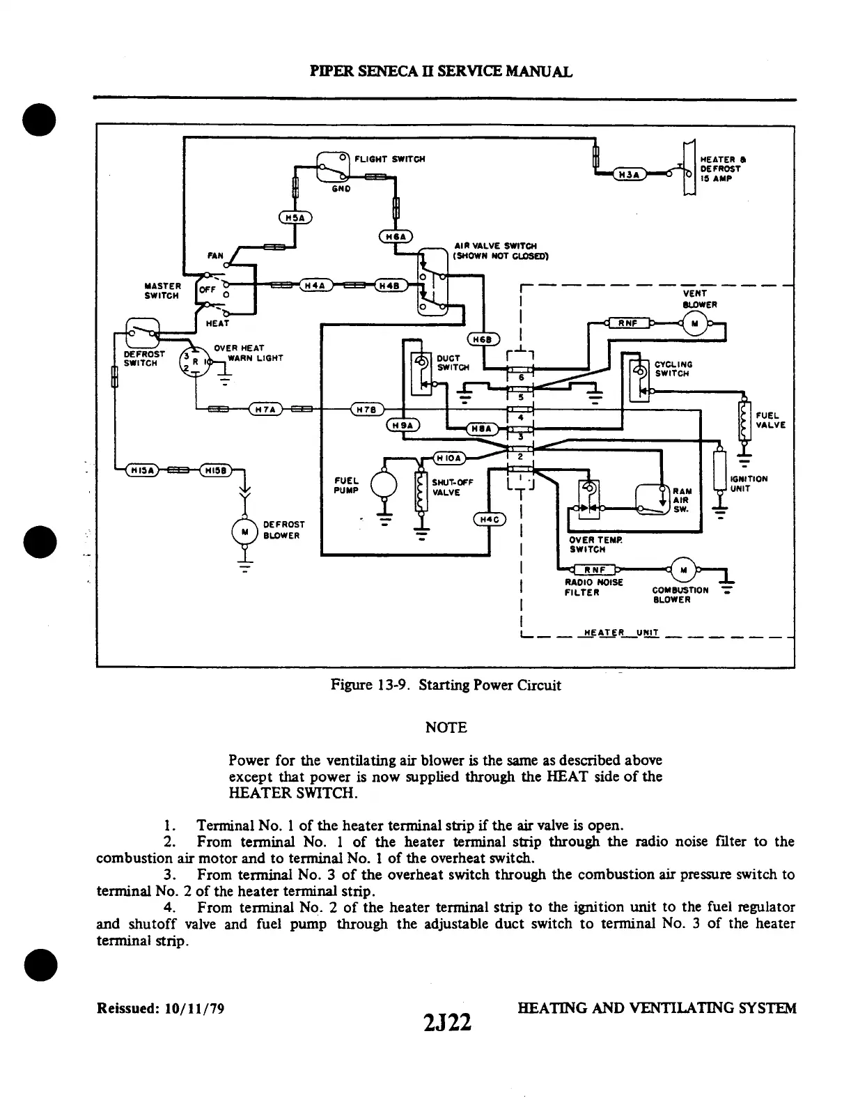
13-9. Starting
Power Circuit
NOTE
Power for the ventilating air blower is the same as described above
except that power is now supplied through the HEAT side of the
HEATER SWITCH.
1. Terminal No. 1 of the heater terminal strip if the air valve is open.
2. From terminal No. 1 of the heater terminal strip through the radio noise filter to the
combustion air motor and to terminal No. 1 of the overheat switch.
3. From terminal
No. 3 of the overheat switch through the
combustion air pressure switch to
terminal No. 2 of
the heater terminal
strip.
4. From terminal No. 2 of
the heater terminal strip to the ignition
unit to the fuel regulator
and shutoff valve and fuel pump through the adjustable duct switch to terminal No. 3 of the heater
terminal
strip.
Reissued: 10/11/79 2J22
2J22
HEATING AND VENTILATING SYSTEM
 Loading...