PIPER
SENECA
II
SERVICE
MANUAL
LIST
OF ILLUSTRATIONS
Figure
Aerofiche
Grid No.
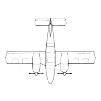
2-1.
Three
View ...............................................................
IA19
2-2.
Station
References
..........................................................
IA20
2-2A.
Torque
Wrench
Formula
...................................................
IB
1
2-3.
Access
Plates
and Panels
....................................................
1B5
2-4.
Jacking
...................................................................
B7
2-5.
Weighing
.................................................................
1 B8
2-6.
Leveling
Airplane
..........................................................
1 B9
2-7.
Turning
Distance
..........................................................
IB14
2-8.
Service
Points
.............................................................
B
16
2-9.
Lubrication
Chart
(Landing
Gear,
Main)
.....................................
IC2
2-10.
Lubrication
Chart (Landing
Gear, Nose)
.......................................
IC3
2-11.
Lubrication
Chart (Control
System)
..........................................
IC4
2-12.
Lubrication
Chart
(Control
System)
(cont.)
...................................
1C5
2-13.
Lubrication
Chart
(Power
Plant and
Propeller)
................................
IC6
2-14.
Lubrication
Chart
(Cabin Door,
Baggage
Doors and
Seats)
.....................
1C7
4-1.
Cherrylock
Rivet
Removal
.....
..........................................
ID15
4-1a.
Hose/Line
Markings
.......................................................
ID16
4-1b.
Flareless Tube
Fittings .....................................................
I D 18
4-1c.
Aileron and
Flap Installation
................................................
ID22
4-2.
Wing
Installation
..........................................................
1E
4-3.
Empennage
Group
....................................
...
..................
IE7
4-4.
Method
of
Securing
Control
Cables
..........................................
I E11
4-5.
Windshield
Installation
.....................................................
E
13
4-6.
Side
Window
Installation
(Typical)
..........................................
I E
14
4-7.
Rear
Door
Window
Replacement
............................................
IE16
4-7a.
Snubber Installation
.......................................................
IE 18
4-8.
Seat
Back Lock
...........................................................
IE23
4-9.
Skin Materials
and
Thickness
...............................................
IF3
4-10.
Surfaces
Scratches,
Abrasions
or Ground-in-Dirt
..............................
IF8
4-11.
Deep
Scratches,
Shallow
Nicks and
Small Holes
...............................
IF8
4-12.
Mixing
of Epoxy
Patching
Compound
.......................................
1F9
4-13.
Welding
Repair
Method ....................................................
1F9
4-14.
Repairing
of Cracks
.....................................................
. IF10
4-15.
Various
Repairs ...........................................................
IF11
4-16.
Repair of
Stress Lines
......................................................
1F12
4-17.
Repair
of Impacted
Damage
................................................
IF12
4-18.
Control
Surface Balance
Tool
...................
............................
1F16
4-19.
Aileron
and
Rudder Balance
Configuration
...................................
IF18
4-20.
Stabilator
Balance
Configurations
...........................................
IF19
5-1.
Control Column
Assembly
..................................................
IG1
5-1a.
Correct
Method of
Installing
Rod End
Bearing ................................
IG4
5-2.
Aileron
Controls
..........................................................
IG5
Revised:
3/16/81
1A5
 Loading...