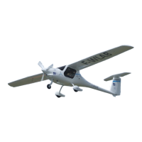
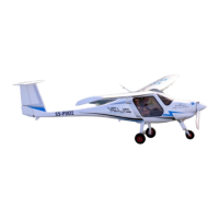
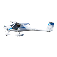
ALPHA Electro
www.pipistrel-aircraft.com
REV.0
POH-167-00-40-150
3-5
Emergency procedures
BPRS
Please refer to Appendix (9-2) for information about the use of Ballistic Parachute Rescue
System during emergency.
Battery failure
With two battery packs on board the battery system is automatically redundant. A failure of one
battery pack will be displayed on EPSI570 as a warning and the system will automatically switch
to a single-battery mode, enabling continuation of flight. Land as soon as practical and have the
battery system verified by authorised personnel.
WARNING! Single battery operation is considered an emergency situation in which the
maximum power output must be kept below 35 kW! Plan actions and maneuvers accordingly.
Ditching
1. Airspeed - Set airspeed for best glide
2. Flaps - set position 0
3. Throttle - cut off
4. Disengage both battery circuit breakers (HV BAT.1/.2)
5. Life vests - check
6. Items in cabin - secure
7. Seat belts - check fastened and tighten
8. Radio - set 121.5 MHz and trasmit “MAYDAY, MAYDAY, MAYDAY, ...”
9. Transponder - Set to 7700
10. Approach - high seas and high wind into the wind, light wind heavy swells
parallel to the coastline
11. Doors - unlatch/ unlock
12. Master - OFF
13. Disengage PWR CTRL circuit breaker
14. Flaps - set to max extension before making contact with the surface
15. Landing - make contact with water surface at the lowest possible speed
16. Seat belts - release immediately
17. Aircraft - exit as soon as possible
18. Life vest and raft - inflate when outside the cabin
Powertrain components overtemperature
Continuous monitoring and a careful management (power setting) of powertrain components tem-
perature is essential for flight safety. Motor, power controller and battery temperatures are displayed
on the EPSI570 screen in the form of vertical bar-type indicators. Temperature ranges (normal, cau-
tion, warning) are indicated beside each vertical bar. Please see Section 2 - Limitations - Motor instru-
ment markings - for applicable temperature range values.