3.4 Internal Patching
Taiga Keyboard utilizes internal patching to create a three oscillator synth voice that does not require patch cables to play.
The default internal patching is meant to create the expected or most commonly used signal path for each function. The
default patch moves the audio and control signals from left to right. The [Control] module manages Midi to CV conversion,
arpeggiator, and digital modulation tools setting the pitch of the oscillator and triggering the envelopes and / or dynamics
controller. The output of [Oscillator 1], [Oscillator 2], [Oscillator 3] is sent to channels 1, 2, 3 of the [Mixer]. The mixer outputs
to the [Pgh Filter]. The output of the lter is sent into the [Dynamics] controller to manage both amplitude and harmonics.
The signal then passes through the [Echos] analog delay before being sent to the main and headphone [Output].
Each default patch will be highlighted and explained in the corresponding individual module section of the manual.
To modify the internal patch or to create something completely new, all of the internal routing can be bypassed using
patch cables. This allows total patching freedom without the constrains of a xed voice architecture. Plugging a patch
cable into an internally patched input jack will override any internal patching. Most internal connections are made using
switched jacks. A switched jack allows the internal signal path to be disabled when a patch cable is inserted. A simple
example would be the [FM Input Jack] of oscillators. Internally, the lfo outputs are wired to the switched jack [FM Input Jack]
of each oscillator. When a patch cable is plugged into the [FM Input Jack] of one of the oscillators, that patch cable breaks
the connection to the lfo output to that oscillator and replaces it with the signal from the inserted patch cable.
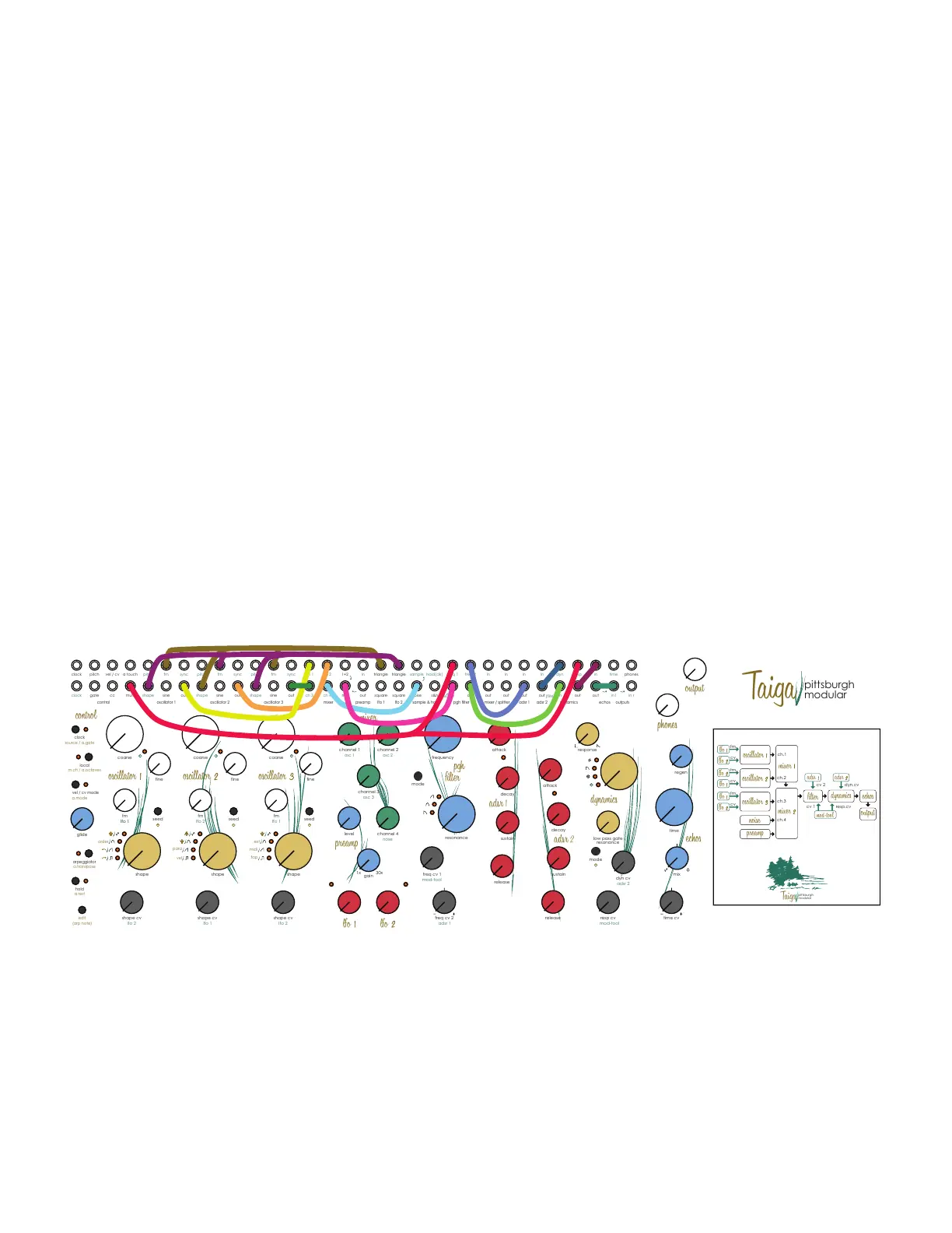
3.5 Internal Patching Diagram:
The diagram below shows the pre-patched audio and CV signals. Each signal is patched with a unique color for clarity.
3 Taiga Keyboard Overview
freq cv 1
echos
preamp
outputs
out
in l
time
out
phones
in r
in
lfo 1
square
triangle
time
clock
clock
pitch
cc
gate
vel / cv
s&h
sample
noise
adsr 2
lfo 2
sample & hold
sine
fm
out
sync
pitch
shape
mixer
oscillator 3
oscillator 2oscillator 1
control
1+2
mix
ch 4
ch 2ch 1
ch 3
pgh filter
mixer / splitter
adsr 1 adsr 2
inin
out
in in
outout out
in
freq 2freq 1
in
out
edit
(arp note)
a.mode
vel / cv mode
a.transpose
order
tap
midi
ext
arpeggiator
a.rest
hold
source / a.gate
clock
m.ch / a.octaves
local
glide
dynamics
out
resp
dyn
in
(filter)
resp cv
dyn cv
response
shape
shape cv
coarse
fine
fm
seed
mode
osc 2
osc 1
noise
1x 30x
osc 3
attack
decay
sustain
lfo 1
fm
lfo 1
lfo 1
shape
shape cv
coarse
fine
fm
seed
lfo 2
lfo 2
shape
shape cv
coarse
fine
fm
seed
lfo 1
release
attack
decay
sustain
release
mix
regen
fm
cv 2 dyn.cv
resp.cv
cv 1
ch.1
ch.2
ch.3
ch.4
mod-tool
mod-tool
lfo 2
square
triangle
low pass gate
resonance
(mix)
hold(clk)
mode
multi
a touch
sine
fm
out
sync
pitch
shape
sine
fm
out
sync
pitch
shape
channel 3
gain
channel 4
channel 1 channel 2
level
pittsburgh
modular
pittsburgh
modular
time cv
_
_
_
resonance
frequency
cv
fm
cv
fm
cv
freq cv 2
adsr 1
_
_
_
vel
para
 Loading...