21
Step 5: Supply power to the 802.3at PoE+ Switch.
A. Connect one end of the power cable to the 802.3at PoE+ Switch.
B. Connect the power plug of the power cable to a standard wall outlet.
When the 802.3at PoE+ Switch receives power, the Power LED should remain solid
Green.
3.2 Rack Mounting
To install the 802.3at PoE+ Switch in a 19-inch standard rack, follow the
instructions described below.
Step 1: Place your 802.3at PoE+ Switch on a hard at surface, with the front
panel positioned towards your front side.
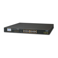
Step 2: Attach a rack-mount bracket to each side of the 802.3at PoE+ Switch
with supplied screws attached to the package. Figure 3-2 shows how to
attach brackets to one side of the 802.3at PoE+ Switch.
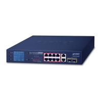
1
PWR
5 9 13 17 21
3 7 11 15 19 23
PoE
2 6 10 14 18 22
4 8 12 16 20 24
PoE
24-Port 10/100/1000T
802.3at PoE
+
2-Port Gigabit
SFP Ethernet Switch
SFP
26
4 6 82
1 3 5 7
12 14 1610
9 11 13 15
20 22 2418
17 19 21 23
PoE Port Status
GSW-2620VHP
PoE In-Use
ACTLNK1000
ACTLNK10/100
ACT
LNK
SFP
25 26
25
Standard
VLAN
Extend
Figure 3-2: Attaching the Brackets to the 802.3at PoE+ Switch.
You must use the screws supplied with the mounting brackets.
Damage caused to the parts by using incorrect screws would invali-
date the warranty.
Step 3: Secure the brackets tightly.
Step 4: Follow the same steps to attach the second bracket to the opposite side.
 Loading...