11
4. Hardware Introduction
4.1 Front Panel
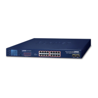
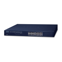
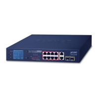
The front panel of the 802.3at PoE+ Switch consists of 16/24 auto-sensing
10/100/1000Mbps Ethernet RJ45 ports. The LED Indicators are also located on
the front panel of the 802.3at PoE+ Switch.
1
3
5
7
9
11
13
15
16
2
4
6
8
10
12
14
17
18
LNK
ACT
Standard
VLAN
17 18
GSW-1820HP
16-Port 10/100/1000T
802.3at PoE
+
2-Port 1000X SFP
Gigabit Ethernet Switch
9 11 13 151 3 5 7
PoE Usage 80%
PWR
1 2 3 4 5 6 7 8 9 10 11 12 13 14 15 16
PoE-in-Use
PoE
1000BASE-X SFP
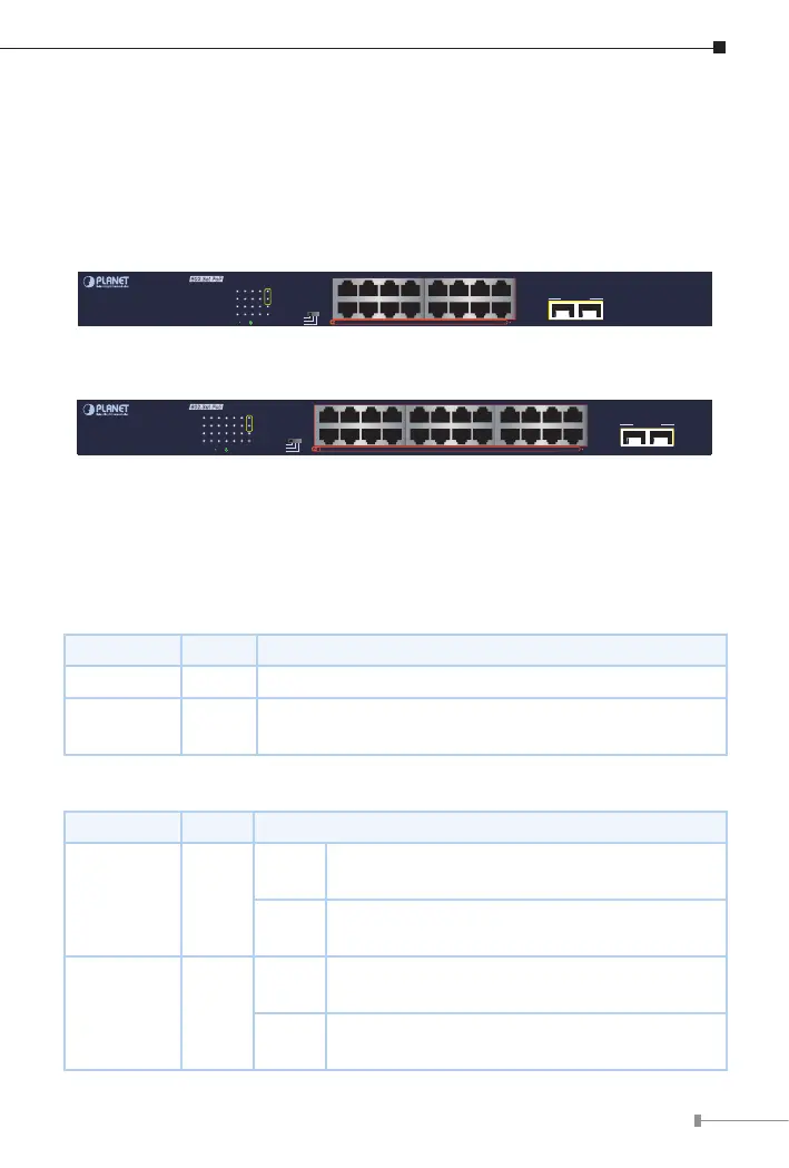
Figure 4-1: GSW-1820HP Switch Front Panel
9 11 13 15 17 19 21 231 3 5 7
25 26
1
3
5
7
9
11
2
4
6
8
10
12
13
15
16
14
17
19
20
18
21
23
24
22
25
26
Standard
Extend
VLAN
PoE Usage 80%
PWR
1 2 3 4 5 6 7 8 9 10 11 12 13 14 15 16 17 18 19 20 21 22 23 24
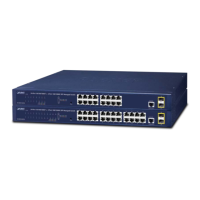
GSW-2620HP
24-Port 10/100/1000T
802.3at PoE
+
2-Port 1000X SFP
Gigabit Ethernet Switch
1000BASE-X SFP
LNK
ACT
PoE
PoE-in-Use
Figure 4-2: GSW-2620HP Switch Front Panel
4.2 LED Indicators
System
LED Color Function
PWR Green Lights to indicate the Switch has power.
PoE Usage
80%
Green
Lightstoindicatethesystemhas80%PoEpower
usage (About 200W).
Per 10/100/1000BASE-T Port
LED Color Function
LNK/ACT Green
Lights
To indicate the link through that port is
successfully established at 10/100/1000Mbps.
Blinks
To indicate that the switch is actively sending
or receiving data over that port.
PoE-in-Use Amber
Lights
To indicate the port is providing DC in-line
power.
O
To indicate the connected device is not a PoE
powered device (PD)
 Loading...