16
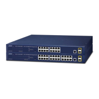
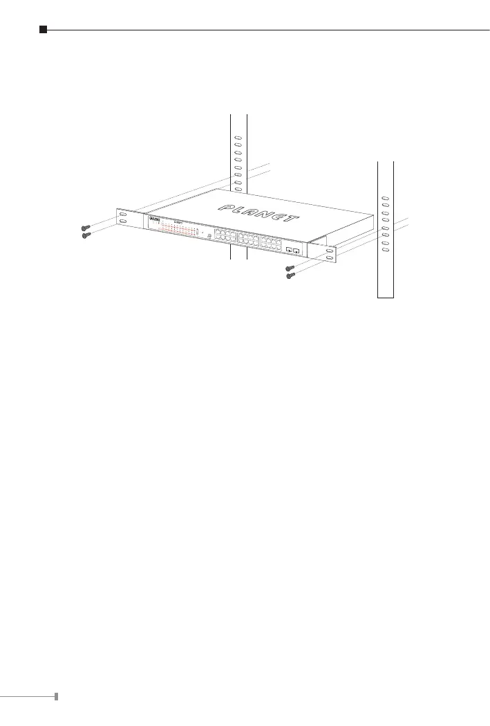
Step 5: After the brackets are attached to the 802.3at PoE+ Switch, use
suitable screws to securely attach the brackets to the rack, as shown
in Figure 5-2.
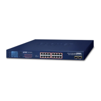
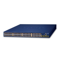
GSW-2824P
PWR
1
2
3
4
1 2 3 4 5 6 7 8 9 10 11 12 13 14 15 16 17 18 19 20 21 22 23 24
5
6
7
8
9
10
11
12
13
14
15
16
17
18
19
20
21
22
23
24
25
26
27
28
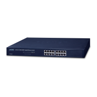
1 2
3 4
5 6
7 8
9 10
11 12
13 14
15 16
17 18
19 20
21 22
23 24
26
25
28
27
27
28
Standard
VLAN
Extend
24-Port 10/100/1000T 802.3at PoE
+
2-Port 10/100/1000T
+
2-Port Gigabit TP/SFP Combo Ethernet Switch
10/100
1000
LNK/ACT
LNK/ACT
PoE-in-Use
1000X SFP
1 3 5 7 9 11 13 15 17 19 21 23
2
PWR
4 6 8 10 12 14 16 18 20 22 24
25
26
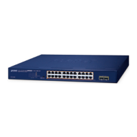
GSW-2620HP
PoE-in-Use
ACTLNK1000
ACTLNK10/100
PoE-in-Use
ACTLNK1000
Standard
Extend
VLAN
25
18 20 22 24
17 19 21 23
10 12 14 16
9 11 13 15
2 4 6 8
1 3 5 7
26
24-Port 10/100/1000T
802.3at PoE
+
2-Port 1000X SFP Gigabit Ethernet Switch
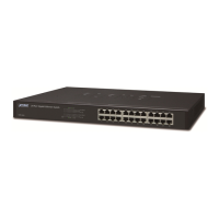
Figure 5-2: Mounting the 802.3at PoE+ Switch in a Rack
Step 6: Connect your 802.3at PoE+ Switch to 802.3af/802.3at complied PDs
and other network devices.
A. Connect one end of a standard network cable to the 10/100/1000BASE-T
RJ45 ports on the front panel of the 802.3at PoE+ Switch.
B. Connect the other end of the cable to the network devices such as
printer servers, workstations or routers, etc.
Step 7: Supply power to the 802.3at PoE+ Switch.
A. Connect one end of the power cable to the 802.3at PoE+ Switch.
B. Connect the power plug of the power cable to a standard wall outlet.
When the 802.3at PoE+ Switch receives power, the power LED should remain
solid Green.
 Loading...