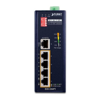
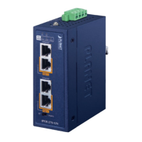
5
Per 10/100BASE-TX Port
LED Color Function
10/100
LNK/ACT
Green
Lights: indicating the port is running at 10/100Mbps speed
and successfully established.
Blinks: indicating that the switch is actively sending or
receiving data over that port.
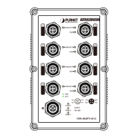
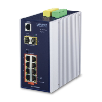
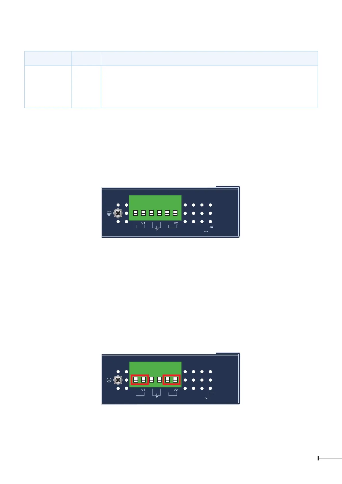
2.3 Switch Upper Panel
The upper panel of the Industrial Ethernet Switch consists of one terminal block
connector within two DC power inputs.
Figure 3 shows the upper panel of the Industrial Ethernet Switch.
Max. Fault Alarm Loading:24V, 1A.
DC Input: 12-48V
, 1.2A max.
AC Input: 24V
, 1.1A max.
Alarm
V1+ V2+
PWR2PWR1
1 2 3 4 5 6
Figure 3: ISW-501T and ISW-801T Top View
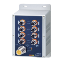
2.4 Wiring the Power Inputs
The Upper Panel of the Industrial Ethernet Switch indicates a DC inlet power socket
and consists of one terminal block connector within 6 contacts. Please follow the
steps below to insert the power wire.
1. Insert positive/negative DC power wires into Contacts 1 and 2 for Power 1, or 5
and 6 for Power 2.
Max. Fault Alarm Loading:24V, 1A.
V1+
V2+
PWR1
PWR2Alarm
DC Input: 12-48V
, 1.2A max.
AC Input: 24V
, 1.1A max.
1 2 3 4 5 6
 Loading...