6
2. Tighten the wire-clamp screws for preventing the wires from loosening.
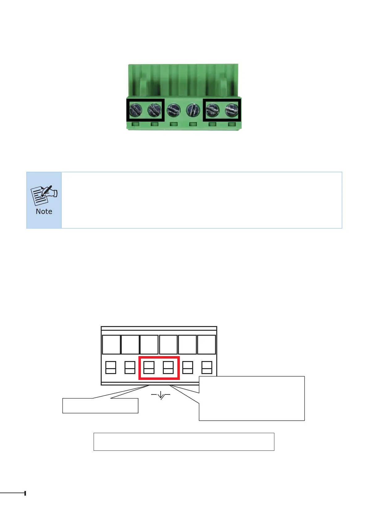
1 2 3 4 5 6
V1+ V1- V2+ V2-
Power 1 Alarm Power 2
1. The wire gauge for the terminal block should be in the range between
12 and 24 AWG.
2. The power input range is DC 12V ~ 48V and supports AC 24V.
3. Use one power input when using AC 24V.
2.5 Wiring the Fault Alarm Contact
The fault alarm contacts are in the middle of the terminal block connector as the
picture shows below. Inserting the wires, the Industrial Ethernet Switch will detect
the fault status of the power failure, or port link failure and then forms an open
circuit. The following illustration shows an application example for wiring the fault
alarm contacts.
Fault Alarm Contacts
The Fault Alarm Contacts are
energized (CLOSE) for normal
operation and will OPEN when
failure occurs
Alarm
Insert the wires into the fault alarm contacts
 Loading...