5
3. Wiring the Power Inputs
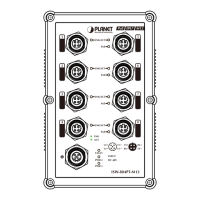
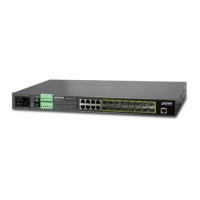
The Front Panel of the Managed Metro Switch consists one terminal block
connector within 6 contacts for DC power source and one power inlet for AC
power source as shown in Figure 3-1.
Reset
1000 LNK/ACT
10/100 LNK/ACT
18 20 2 4
2Alarm
DC1
DC2
AC
4 6 8 10 12 14 16
17 19 1 3
1 3 5 7 9 11 13 15
ON
AC POWER
OFF 50/60Hz
100-240V , 1.5A max.100-240V , 1.5A max.
DC POWER
ON
OFF
DC Input: 36-60V
,
1.5A max.
Alarm
GNDGNDDO 1DO 0DI 1DI 0
DC 2DC 1
CAUTION
Please refer to user’s manual before
connect the DC wire.
Max. Fault Alarm Loading: 24V, 1A
1G/2.5G
100/10G
XG
Figure 3-1: MGSW-24160F Inlet Power Socket
Users can plug the Managed Metro Switch into either AC or DC power source
for the connectivity. The specications of the DC/AC power source are as
follows.
Power source
DC:36-60V,1.5AMax.
AC:100-240V,50/60Hz,1.5AMax.
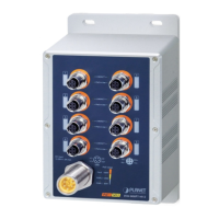
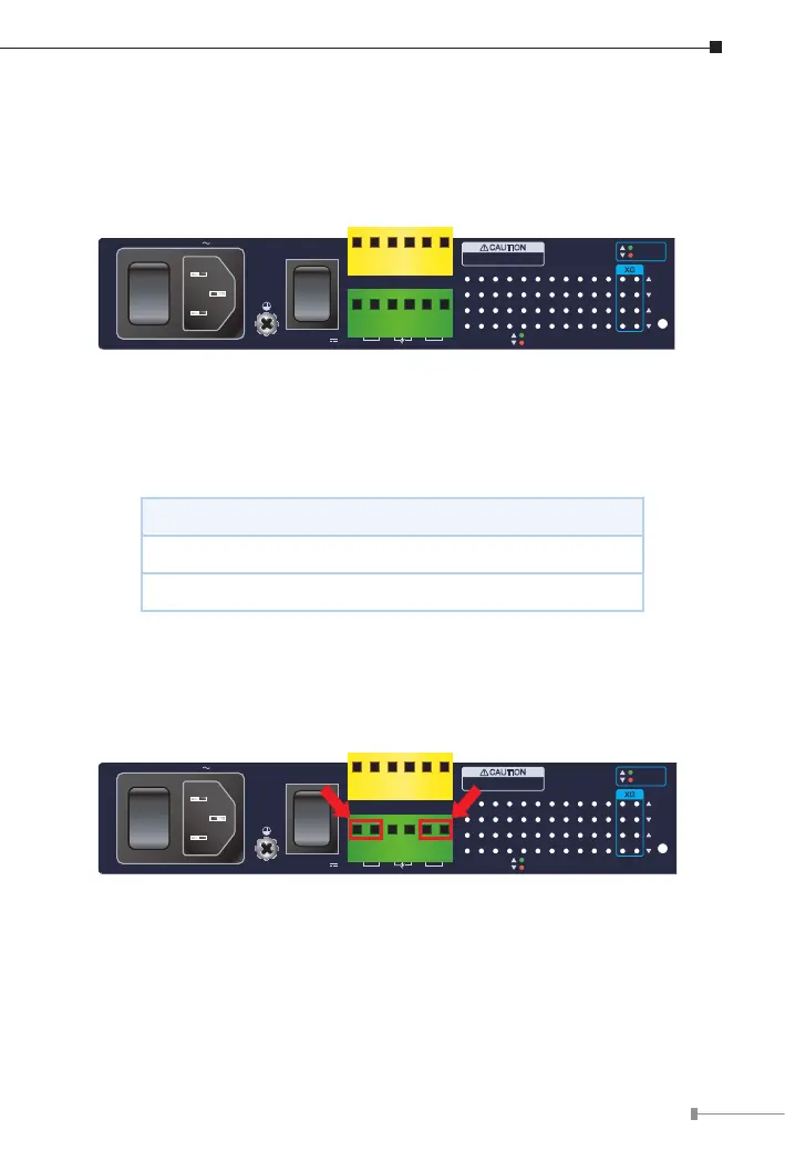
For wiring DC power inputs, please follow the steps below to insert the
power wires.
1. Insert positive and negative DC power wires into contacts 1 and 2 for DC
power 1, or 5 and 6 for DC power 2.
Reset
1000 LNK/ACT
10/100 LNK/ACT
18 20 2 4
2Alarm
DC1
DC2
AC
4 6 8 10 12 14 16
17 19 1 3
1 3 5 7 9 11 13 15
ON
AC POWER
OFF 50/60Hz
100-240V , 1.5A max.100-240V , 1.5A max.
DC POWER
ON
OFF
DC Input: 36-60V
,
1.5A max.
Alarm
GNDGNDDO 1DO 0DI 1DI 0
DC 2DC 1
CAUTION
Please refer to user’s manual before
connect the DC wire.
Max. Fault Alarm Loading: 24V, 1A
1G/2.5G
100/10G
XG
Figure 3-2: 6-contact Terminal Block Connector
 Loading...