6
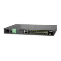
2. Tighten the wire-clamp screws to prevent the wires from loosening.
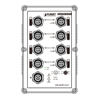
1 2 3 4 5 6
DC 1 Alarm DC 2
+ - + -
Figure 3-3: Screws of 6-contact Terminal Block Connector
1. The wire gauge of the terminal block should be between 12
and24AWG.
2. DC1 and DC2 must provide exactly the same DC voltage for
power load balance while operating with dual power input.
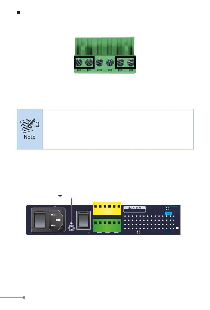
3.1 Grounding the Device
Users MUST complete grounding wiring with the device; otherwise, a sudden
lightning could cause fatal damage to the device.
Reset
1000 LNK/ACT
10/100 LNK/ACT
18 20 2 4
2Alarm
DC1
DC2
AC
4 6 8 10 12 14 16
17 19 1 3
1 3 5 7 9 11 13 15
ON
AC POWER
OFF 50/60Hz
100-240V , 1.5A max.100-240V , 1.5A max.
DC POWER
ON
OFF
DC Input: 36-60V
,
Alarm
GNDGNDDO 1DO 0DI 1DI 0
DC 2DC 1
CAUTION
Please refer to user’s manual before
connect the DC wire.
Max. Fault Alarm Loading: 24V, 1A
1G/2.5G
100/10G
XG
Earth Ground
Figure 3-4: MGSW-24160F Earth Grounding
 Loading...