Rev 6.3.0 12.09.16
PL Reference Manual
35
A
LOAD
PL20 1N5404 (or 1N5405/06/07)
PL40 1N4007 (or similar)
PL60/
PL80
‘G’ Terminal
1N4007 (or similar)
PL40 1N4007 (or similar)
PL20 1N4007 (or similar)
PL60/
PL8
0
1N5404 (or 1N5405/06/07)
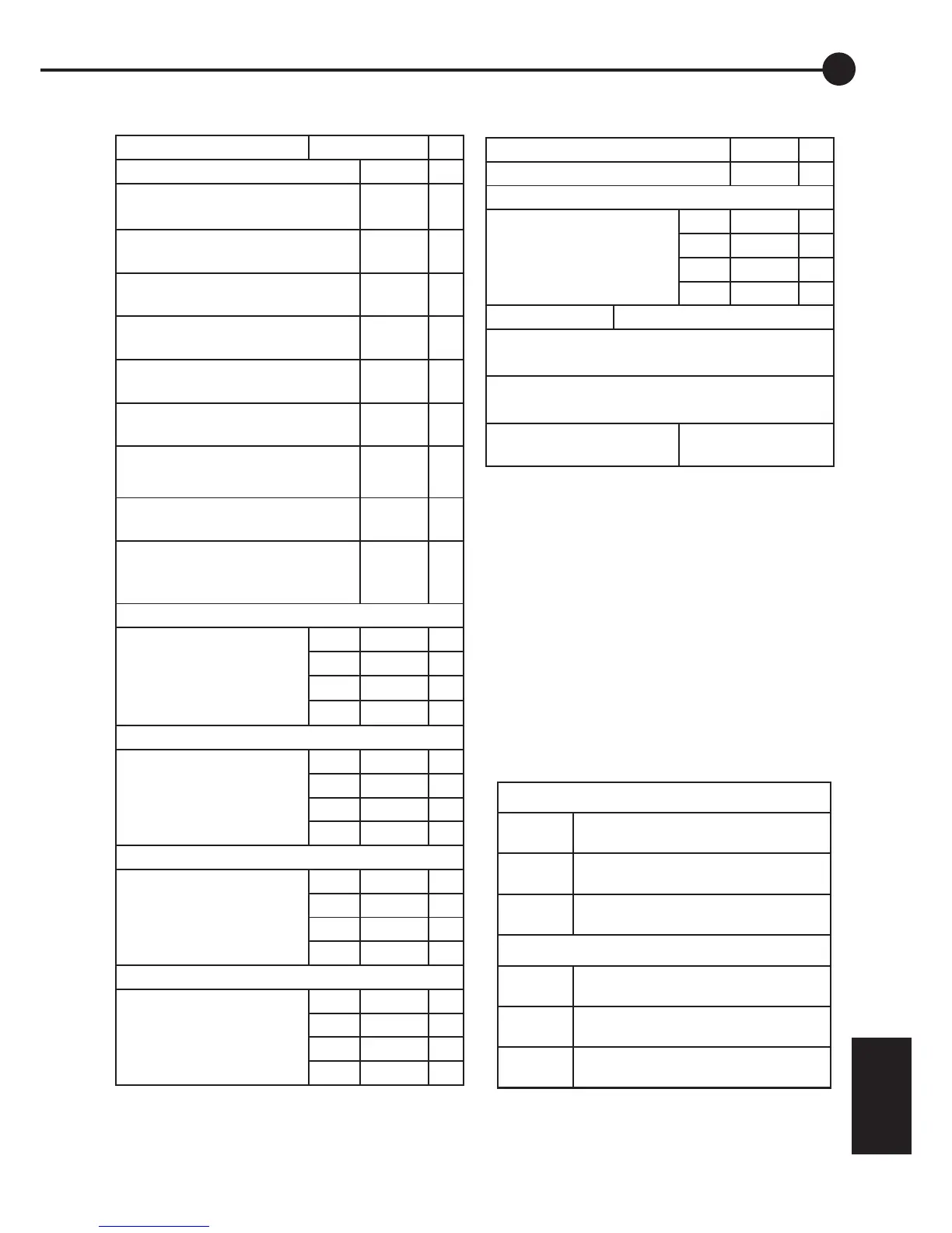
A.2 Specifications on PL20, 40, 60, 80
Nominal system voltages 12,24,32,36,48 V
Maximum voltage BAT+ to BAT- 100 V
Max short term voltage BAT+ (also
SOL+) to BAT-
120 V
Maximum voltage BAT+ to SOL-
(solar voltage Voc) 48V system
100 V
Maximum voltage BAT+ to SOL-
(solar voltage Voc) 24V system
80 V
Maximum voltage BAT+ to SOL-
(solar voltage Voc) 12V system
70 V
Max voltage LOAD- to BAT-
(PL20/PL40)
60 V
Max voltage LOAD- to BAT-
(PL60/PL80)
75 V
Max voltage “G” terminal to BAT-
(PL20/PL40)
60 V
Max voltage between the “G”relay
terminals (PL60/PL80)
85 V
Max voltage B- sense to BAT-
(Reads ±8V where -8V=0, 0V=80,
+8V=160)
+/-10 V
Max. continuous charge current (SOL-)
PL20 20 A
PL40 40 A
PL60 60 A
PL80 80 A
Max. continuous load current (LOAD-)
PL20 20 A
PL40 7 A
PL60 30 A
PL80 40 A
Max. short term* load current
(*a few mins) PL20 25 A
PL40 10 A
PL60 40 A
PL80 50 A
Max “G” terminal output current
PL20 120 mA
PL40 120 mA
PL60 300 mA
PL80 300 mA
A.3 ‘Catch diode‘ protection
Battery Temp sensor range -5 to 50 °C
Max. storage temperature 70 °C
Supply Current
PL20 9 mA
PL40 14 mA
PL60 20 mA
PL80 26 mA
Meter Accuracy <+/-2% +/-1 display digit
Max wire size, Large square screw terminals
PL20/PL40 (PL60/PL80 load) =16mm
2
= 6 AWG
Wire size, Green Terminal Block
= 0.14 - 0.15mm
2
= 26-16 AWG
PL60/PL80 termination
stud
6mm diameter