EasyManua.ls Logo

Plasmatronics PL40 - A.4 Hardware Block Diagrams; PL20;40 Hardware Block Diagram; PL60;80 Hardware Block Diagram

Plasmatronics PL40
43 pages
Print Icon
To Next Page IconTo Next Page
To Previous Page IconTo Previous Page
Loading...
Rev 6.3.0 12.09.16PL Reference Manual
36
SOLAR
(SOL-)
LOAD-BATTERY
(BAT-)
REVERSE
BLOCKING
FET SWITCH
FET SWITCH
SHUNT
SHUNT
PUSH
BUTTON
POWER
SUPPLY
MICRO
CONTROLLER
DISPLAY
TEMPERATURE
SENSOR(T+,T-)
B- SENSE INPUT (B-)
SERIAL PORT
“G” Terminal
BATTERY+
(BAT+)
SOLAR BATTERY LOAD
REVERSE
BLOCKING
FET SWITCH
FET SWITCH
SHUNT
SHUNT
POWER
SUPPLY
MICRO
CONTROLLER
DISPLAY
TEMPERATURE
SENSOR (T+,T-)
BATTERY SENSE
SERIAL PORT
"G" Terminal
NEG NEG NEG
-
-
-
(B+ SENSE,
B- SENSE)
+
+
+
SOL
POS
BAT
POS
LOAD
POS
PUSH
BUTTON
A
A.4.1 Block Diagram of PL20/40 Hardware
The PL Controller is designed for common positive installations (i.e. switches solar and load in the negative wire).
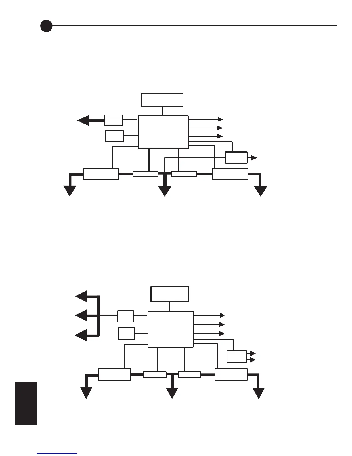
It has a reverse blocking mosfet switch between the SOL- terminal and the BAT- terminal and a mosfet
switch between the LOAD- terminal and the BAT- terminal. There is also a low current mosfet switch
between the ‘Gterminal and the BAT- terminal used to drive a generator control or alarm relay.
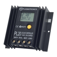
A.4.2 Block Diagram of PL60/80 Hardware
Note: Common positive configuration (ie switches solar and load in the negative wire)

Related product manuals