84
L510001-05
INSTRUMENTATION WIRING DIAGRAMS - 16
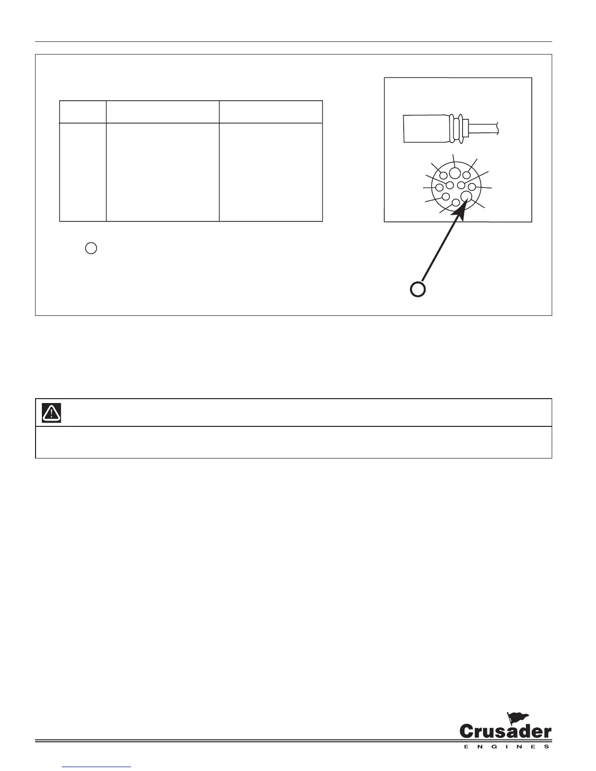
Figure 16-1 Typical Instrumentation Wiring
CIRCUIT CIRCUIT ENGINE HARNESS
NUMBER NAME WIRE COLOR
1. GROUND BLACK
2. TACHOMETER GRAY
3. WATER TEMPERATURE TAN
4. ENGINE ALARM TAN/BLACK
5. IGNITION PURPLE/WHITE
6. BATTERY RED/WHITE
7. STARTER YELLOW/RED
8. OIL PRESSURE LT. BLUE
9. CHECK ENGINE LIGHT BROWN/WHITE
10. DATA LINE ORANGE/BLACK
NOTE: ENGINE HARNESS WIRED FOR PANELS USING VOLTMETERS ONLY.
NOTE
A
: POWER FOR A FUSED ACCESSORY PANEL MAY BE TAKEN FROM
THIS LOCATION. LOAD CANNOT EXCEED 30 AMPS.
WIRE HARNESS COLOR CHART
10
4
3
2
ENGINE
HARNESS
5
6
7
9
8
1
A
NOTE: The light green wire, pigtail, located near the engine harness
connector is for connection of a buzzer or light to indicate low oil pressure.
IMPORTANT: Your engine is designed to work with the standard electronics installed in your boat. If you add other
electrical components or accessories, you could change the way the fuel injection controls your engine or the overall
electrical system functions. Before adding electrical equipment, consult your dealer. If you don’t, your engine may not
perform properly.
CAUTION
Add-on equipment may adversely affect the alternator output or overload the electrical system. Any damage caused
as a result will not be covered by, and may void, your warranty.